
Principle: In a circuit, electric current flows from higher potential locations to lower potential locations. Potential is measured in Volts (symbol V), relative to some ground point. This is similar to how we measure altitude. Altitude is your height in meters relative to the ground. But what we choose as ground depends on our needs. Airplane and mountain altitudes are measured relative to sea level. Parachutists measure altitude relative to the ground they are going to hit. The positive bus in our circuits is at +5 V compared to the ground at 0 V. In some circuits there are potentials below ground, in which case they will have negative voltages.Remember your circuit safety!
 |
 |
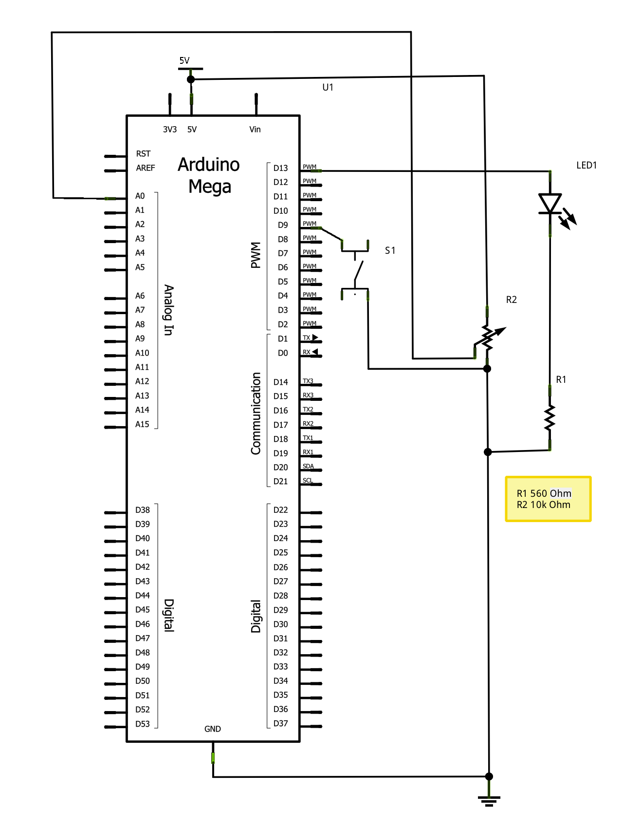 | |
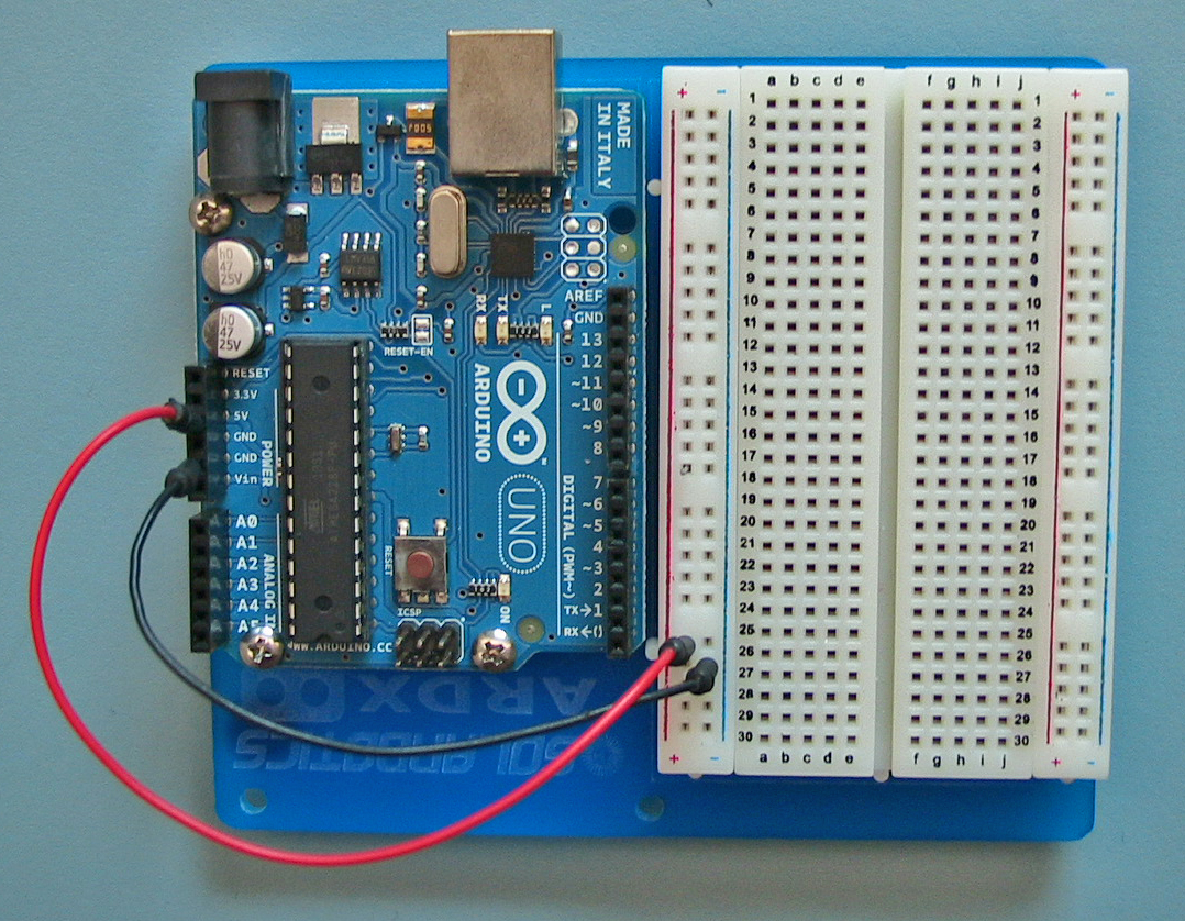
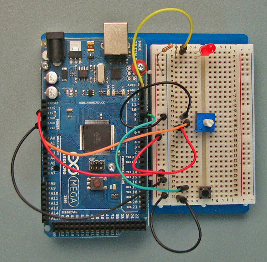
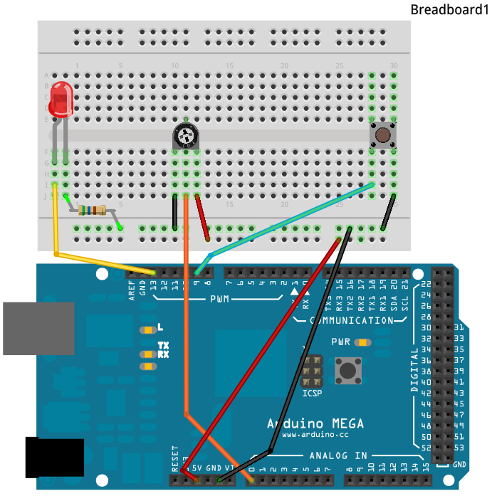
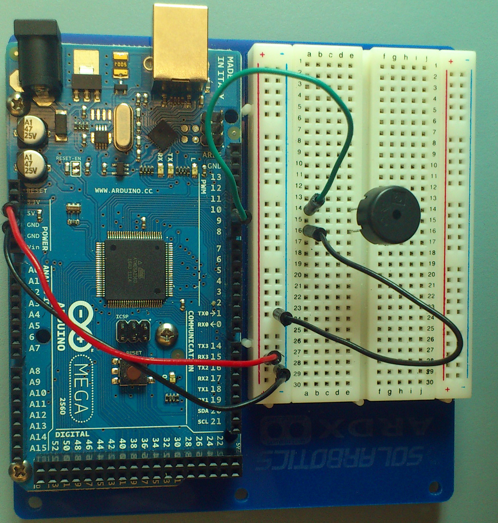
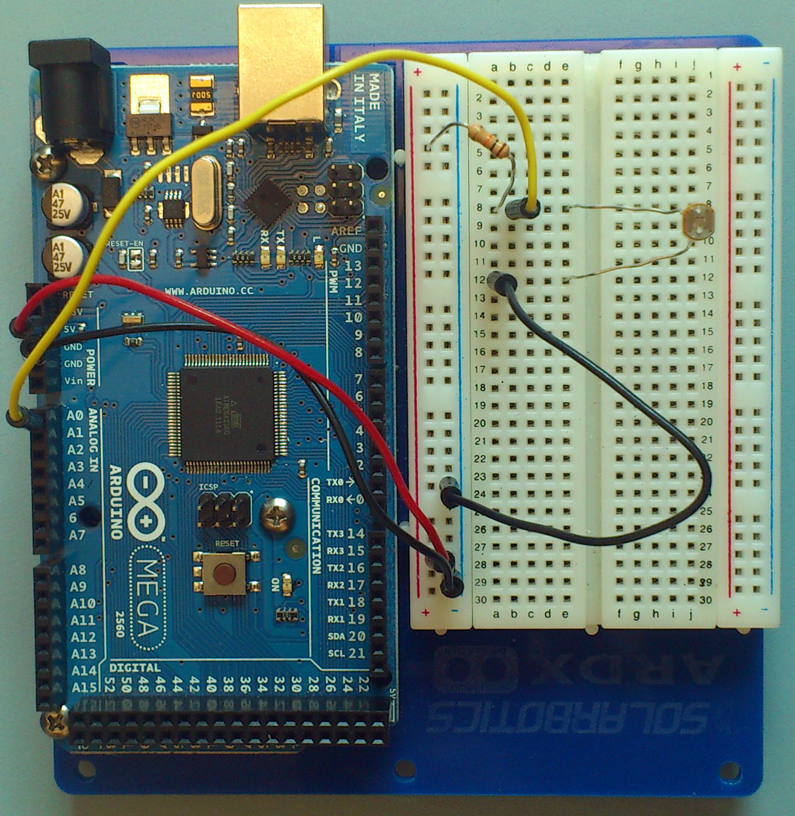
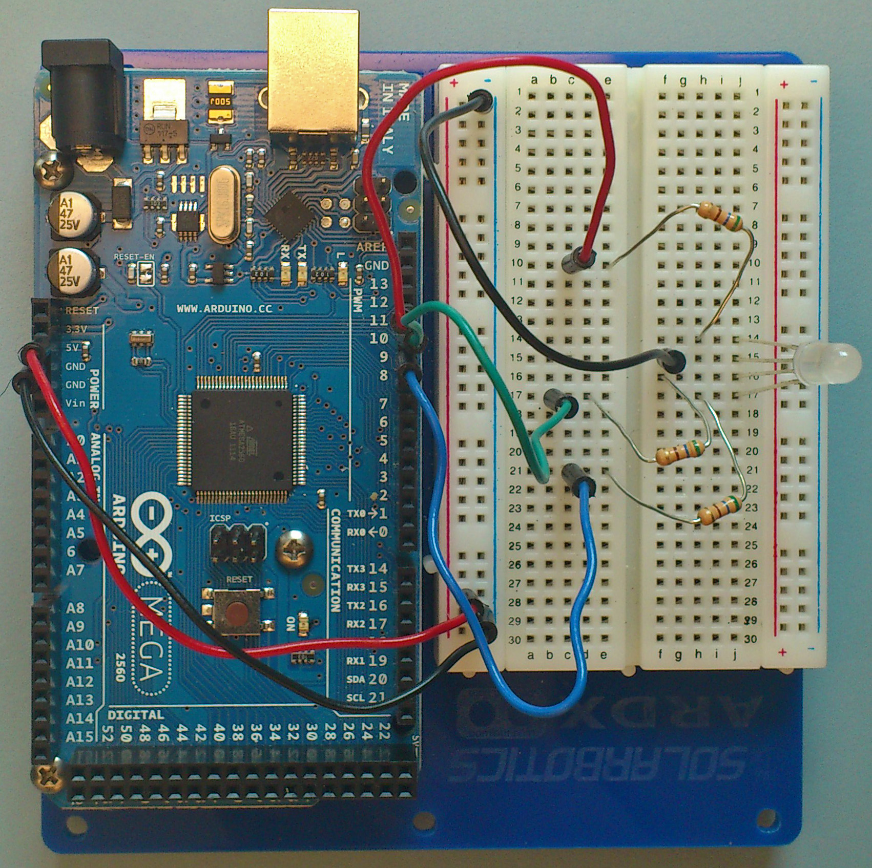
| Photograph | Fritzing | Circuit | |
| Click the image for full size! | |||
 |
The intensity of a LED is controlled by turning it off and on very rapidly. Your eye cannot see the flashes, but it can detect the proportion of on and off time. The more on the LED is, the brighter it appears to you. This on-off timing relationship is called a duty cycle. Duty cycle describes the proportion of one unit of time during which the device is on. |
analogOutput function. You give the function a digital pin number and a duty cycle value (from 0 to 255) where 0 is 0% and 255 is 100%. 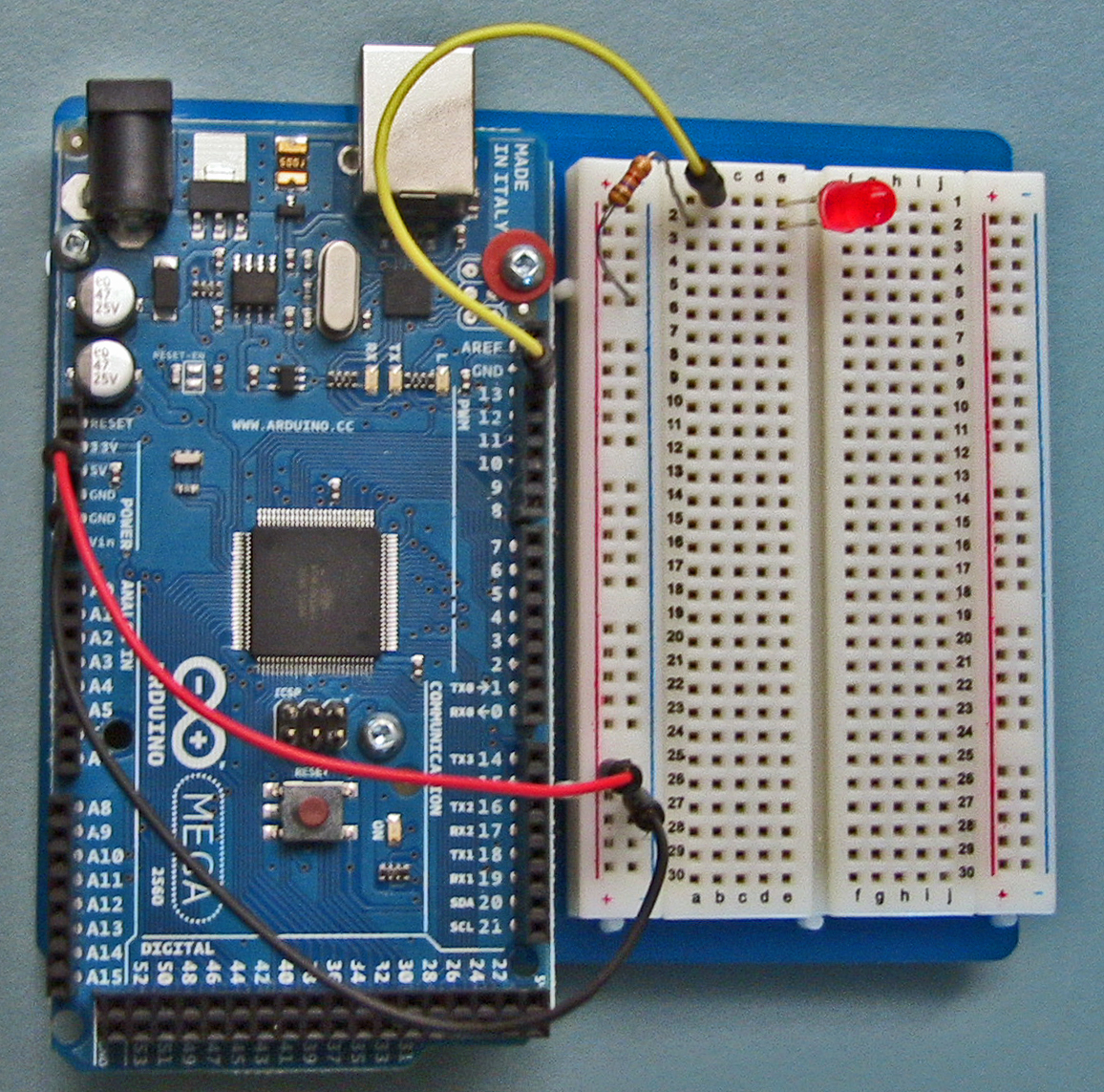
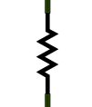 |
Principle: The amount of current flowing in a circuit is measured in Amps (symbol A). Current, voltage, and resistance are related by the relationship Reality Check: In an LED circuit, the voltage E is 5V, the resistance R is 560 Ω, and so the current I is 5 / 560 = 0.009 A. Or, since we typically have small currents in our circuits, the current is 9 mA (milli Amps). |
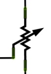 |
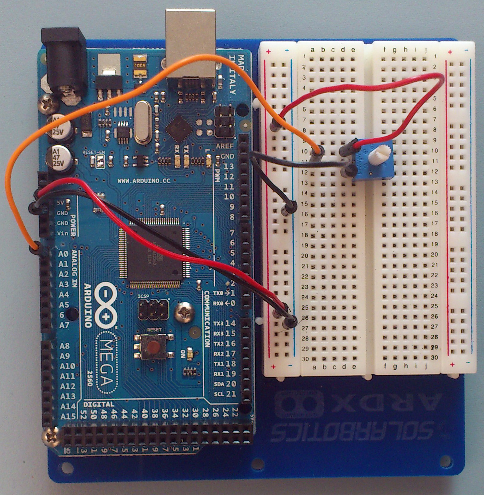
A potentiometer is a special kind of resistor. It has three pins. The outer pins are connected to the ends of the resistor. The middle pin is connected to a slider that moves between the ends of the resistor. If the outer pins are connected between +5 V and 0 V (GND), then the voltage on the middle pin will vary between 5 and 0 V, depending on whether it is closer to the 5V end or closer to the 0 end. |
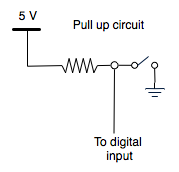 |
Concept: If a digital input pin is not connected to anything, it is said to be floating. Reading from a floating pin is very unreliable. It might be HIGH, but can be LOW. So to ensure that a proper voltage is always present on a digital input, a pullup circuit is used. The resistor attached to the pin is called a pull up resistor. It's job is to ensure that the digital input pin has 5V present when the switch is open. Then when the switch is closed it pulls down the voltage to 0V. You can install the pull up resistor yourself. But this is such a common issue that the Arduino processor has built in pull up resistors that can be turned on. |
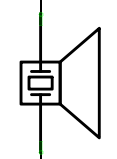 |
The Arduino does not have built in analog outputs. So if you connect a digital output to a speaker, you do not get very smooth excursions. Instead you get a (roughly) square wave. But we still perceive these square waves as tones. |
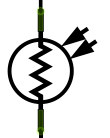 |
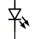
When the illumination on a surface is of a particular color, then the photoresistor can be used to sense how well that color is reflected or absorbed by the surface. By measuring the amount of red, green, and blue coming from the surface we can detect the color of the surface. | It looks like this 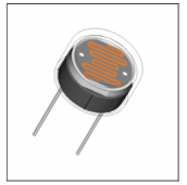 |
| 8. Building Circuits Arduino Intro Labs for Tangible Computing / Version 1.00 2012-09-24 |