Principle: In a circuit, electric current flows from higher potential locations to lower potential locations. Potential is measured in Volts (symbol V), relative to some ground point. This is similar to how we measure altitude. Altitude is your height in meters relative to the ground. But what we choose as ground depends on our needs. Airplane and mountain altitudes are measured relative to sea level. Parachutists measure altitude relative to the ground they are going to hit. The positive bus in our circuits is at +5 V compared to the ground at 0 V. In some circuits there are potentials below ground, in which case they will have negative voltages.The two innermost regions are divided by a vertical groove. Each of the 5 pins in a horizontal row are connected together. These rows are used to make connections for the components of your circuit. The grove down the middle lets you plug in more complex components, many of which are integrated circuits.
setup and loop. setup procedure is called once, and the loop procedure is called as often as possible. The moment that it returns it will be called again. Thus an Arduino program keeps running until you reset the computer. ledPin, and set it to an initial value. pinMode procedure that sets the interface direction of a pin to INPUT (coming from outside the Arduino) or OUTPUT (going to outside the Arduino). digitalWrite procedure send a HIGH or LOW signal to a digital output pin. delay procedure to cause the Arduino to pause for a given number of milliseconds. // the onboard LED is attached to pin 13 |
int ledPin = 13; |
|
/* |
When the Arduino board is reset, this method is |
run exactly once. Its job is to put the board into |
the proper configuration. |
*/ |
void setup() { |
// configure ledPin to be a digital output |
pinMode(ledPin, OUTPUT); |
} |
|
/* |
An Arduino program is generally not meant to stop. |
It is supposed to keep interacting with its environment. |
The loop method is run over and over until the power |
is removed from the board, or the board is reset. |
*/ |
void loop() { |
// set the pin to output a HIGH value and turn the LED on |
digitalWrite(ledPin, HIGH); |
|
// wait for 1000 milliseconds |
delay(1000); |
|
// set the pin to output a LOW value and turn the LED off |
digitalWrite(ledPin, LOW); |
|
// wait for 1000 milliseconds |
delay(1000); |
} |
Concept: A program is composed of different kinds of parts. Some parts are used to declare things, such as the name and type of a variable. Other parts perform actions, such as invoking the procedure that turns on the LED.
Concept: A variable is an item of data in a program. Most variables have names (or identifiers). Every variable has a value. As the program runs the value of a variable can change. Variables can store values that have a specific kind of types, for example integer or character.
A variable must be declared before the program can use it. The declaration gives: the name of the variable, its type, and possibly an initial value. For example, the statementdeclares a variable called int ledPin = 13;ledPinwhich is of typeint(an integer number between -32768 and 32767), and gives it the initial value of 13, which indicates which pin the LED is hooked up to. The semi-colon (;) at the end is important because it signifies the end of the declaration.
Concept: We can take a sequence of program statements and place them into a named collection called a procedure. We can then perform these statements at a specific point in the program by using a procedure invocation. Procedures can have parameters and return a result. For example, the statement:invokes the digitalWrite(ledPin, LOW);digitalWriteprocedure (that is defined elsewhere) with two parameters. Procedures can be identified by having two parentheses following the name of the procedure such asdelay(). If a procedure requires parameters they are placed inside the parentheses, each one separated by a comma as shown withdigitalWrite(). Procedures can also be called methods, functions or subroutines. The parameters are one way to pass information to the procedure, and the result is one way to get information out of the procedure. There are other ways.
The first parameter in the statement above isledPinwhich says which digital I/O pin to use (recall thatledPinhas a value of 13, the pin the LED is connected to), the second parameter isLOWwhich means the low output value. The result is to set the output of the pin to theLOWvalue. The procedure does not return a result.
 |
 |
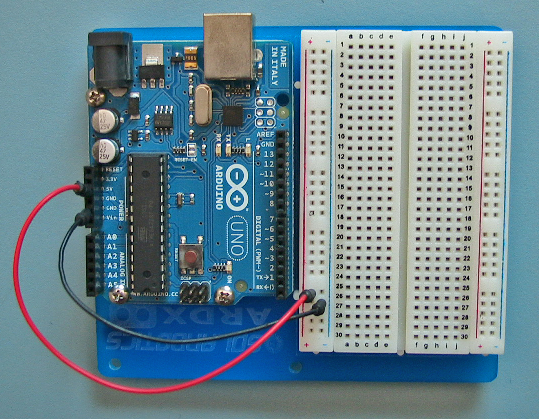
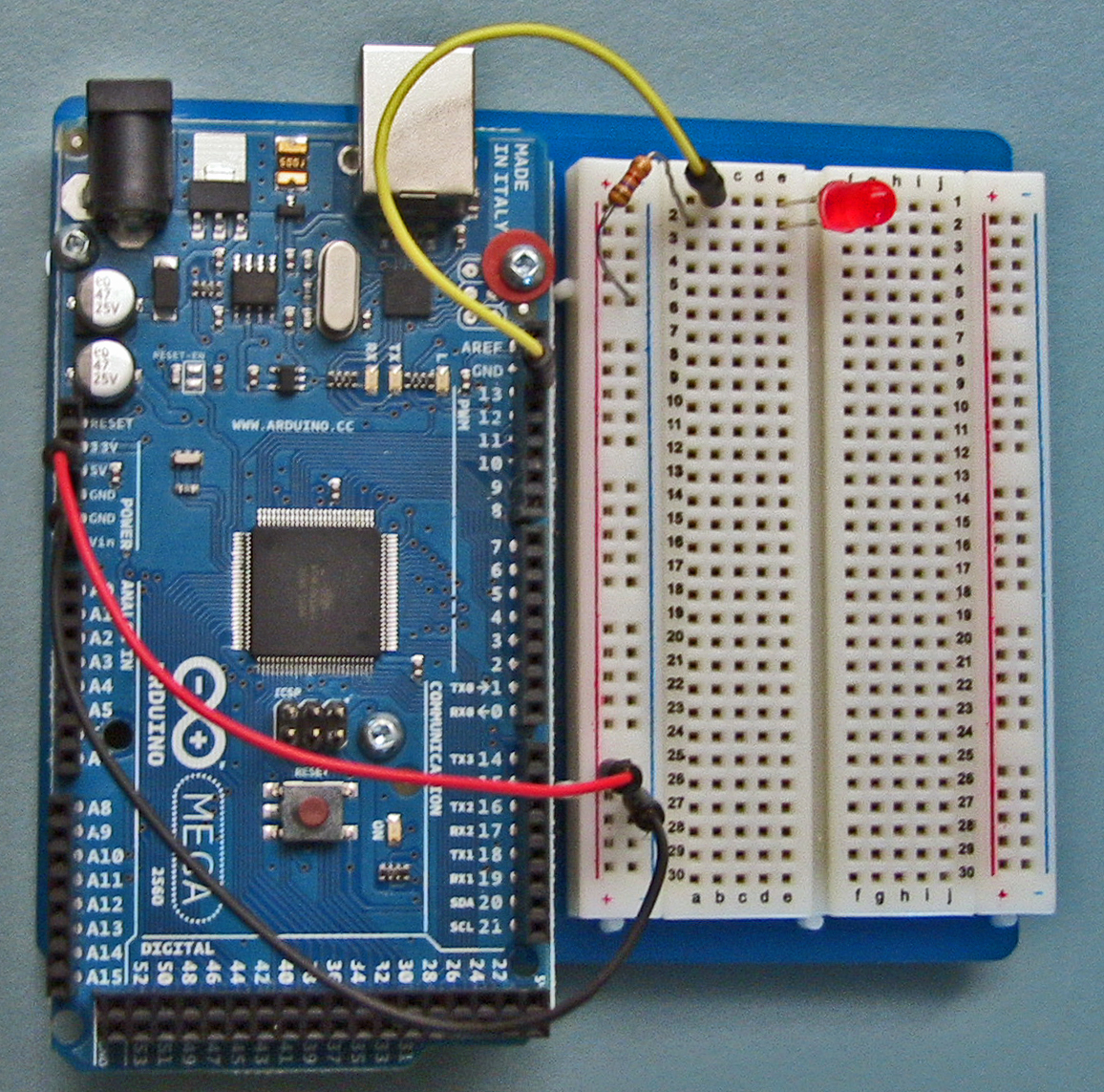
| Arduino Mega | Arduino Uno |
| Click the image for full size! | |
Principle: The amount of current flowing in a circuit is measured in Amps (symbol A). Current, voltage, and resistance are related by the relationshipLight Emitting Diode: The LED is the common replacement for the incandescent light bulb. (See LED). LEDs comes in various colors. There are two very important things to remember about LEDs.E = I R where E is the potential difference measured in Volts, I is the current measured in Amps, and R is the resistance measured in Ohms.
Reality Check: In our circuit, the voltage E is 5V, the resistance R is 560 Ω, and so the current I is 5 / 560 = 0.009 A. Or, since we typically have small currents in our circuits, the current is 9 mA (milli Amps). Why do we have a resister in series with the LED? The resistance of the LED when it turns on is very small, so without a resistor the current that flows is large, and the resulting energy will burn out the LED. A typical LED should not have a current above 20 mA. So 9mA with our resistor is safe.
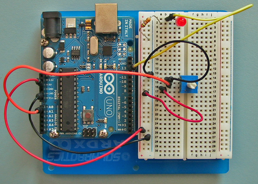
Concept: A potentiometer is a special kind of resistor. It has three pins. The outer pins are connected to the ends of the resistor. The middle pin is connected to a slider that moves between the ends of the resistor. If the outer pins are connected between +5 V and 0 V (GND), then the voltage on the middle pin will vary between 5 and 0 V, depending on whether it is closer to the 5V end or closer to the 0 end.
analogRead function, the program can read the voltage and convert it into an integer value that is then used to set the delay time on the flashing light of Part 1 and 2. Keep the same wiring as before. All we are doing is adding a potentiometer. See the images below the code. // the external LED is attached to this pin. |
// onboard LED is attached to pin 13, |
int ledPin = 13; |
|
// slider of potentiometer attached to this analog input |
int analogInPin = 0; |
|
// On and off time in milliseconds for the light |
int delayTime = 300; |
|
void setup() { |
// configure ledPin to be a digital output |
pinMode(ledPin, OUTPUT); |
} |
|
void loop() { |
// read the voltage on the analog input and convert |
// into an integer value in the range [0, 1023] |
delayTime = analogRead(analogInPin); |
|
digitalWrite(ledPin, HIGH); |
delay(delayTime); |
|
digitalWrite(ledPin, LOW); |
delay(delayTime); |
} |
|
 |
 |
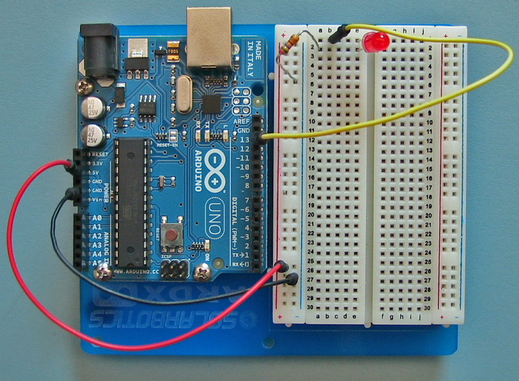
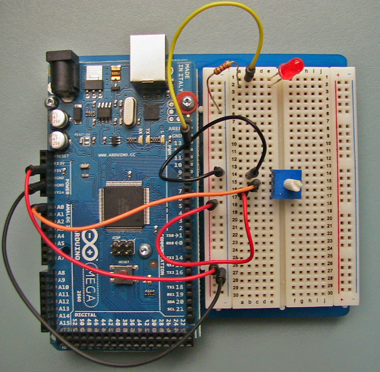
| Arduino Mega | Arduino Uno |
| Click the image for full size! | |
Concept: A procedure invocation can return a result. This result can appear in a statement. For example, the statementinvokes the delayTime = analogRead(analogInPin);analogReadprocedure on the pin whose number is the value in variableanalogInPin. It returns the result (an integer from 0 to 1023) and this is then stored in the variabledelayTime.
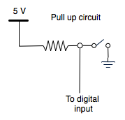 |
Concept: If a digital input pin is not connected to anything, it is said to be floating. Reading from a floating pin is very unreliable. It might be HIGH, but can be LOW. So to ensure that a proper voltage is always present on a digital input, a pullup circuit is used. The resistor attached to the pin is called a pull up resistor. It's job is to ensure that the digital input pin has 5V present when the switch is open. Then when the switch is closed it pulls down the voltage to 0V. You can install the pull up resistor yourself. But this is such a common issue that the Arduino processor has built in pull up resistors that can be turned on. This is done in the setup code of the program. |
 |
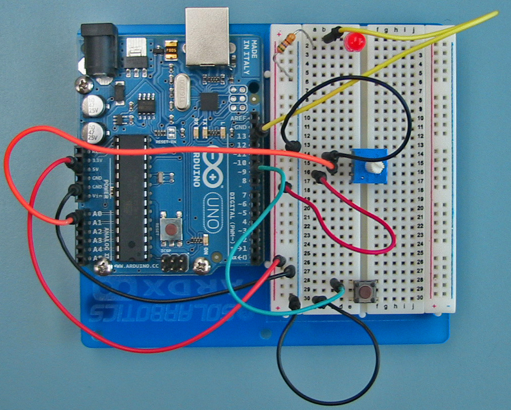 |
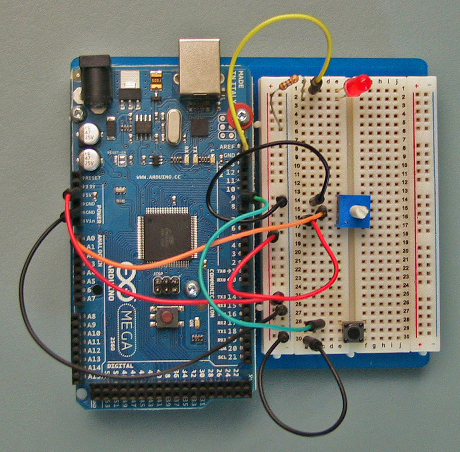
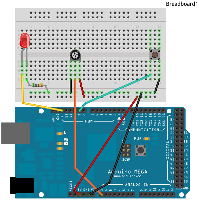
| Arduino Mega | Arduino Uno |
| Click the image for full size! | |
 |
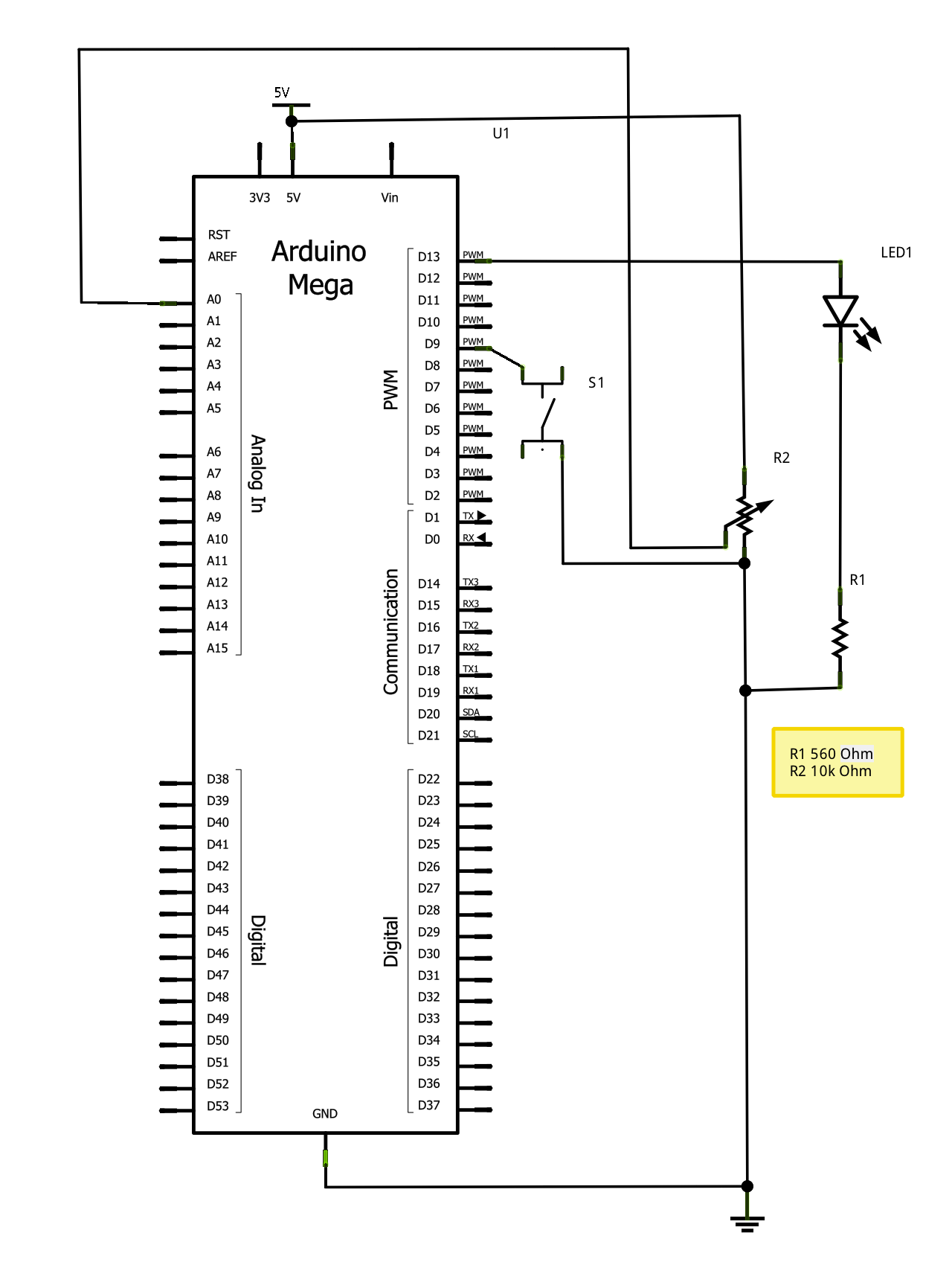 |
| Fritzing | Schematic |
| Click the image for full size! | |
// the LED is attached to this digital output pin |
int ledPin = 13; |
|
// the pushbutton is attached to this digital input pin |
int buttonPin = 9; |
|
// the value read by the pin. |
int buttonValue; |
|
void setup() { |
// set ledPin to OUTPUT |
pinMode(ledPin, OUTPUT); |
|
// set buttonPin to INPUT and |
// turn on internal pull up resistor |
pinMode(buttonPin, INPUT); |
digitalWrite(buttonPin, HIGH); |
} |
|
void loop() { |
// read the pushbutton state |
buttonValue = digitalRead(buttonPin); |
|
// and set the light to be the same value |
digitalWrite(ledPin, buttonValue); |
} |
|
Concept: TheTo make a decision you need to determine if something is true or false, using a logical expression.ifstatement is used to make decisions, and change the behaviour of a program. The if statement comes in two forms
if ( logical expression ) {

     block of statements to perform when logical expression is true

 }

 else {

     block of statements to perform when logical expression is false

 }
or if there is nothing to be done in the false case:
if ( logical expression ) {Almost anything that is proper code can appear inside the block of statements, including additional conditional statements. This is called nesting and it is very important when you only need the first condition to be true and other times you need the first condition and an additional condition to both be true. This will become important in another lab.
block of statements to perform when logical expression is true
}
Concept Logical expressions are typically comparisons, likeor expressions that result from combining comparisons using the logical operations of AND, OR, and NOT which you may or may not have seen before. The code below demonstrates how conditional statements can used. Here we used a conditional statement to turn the LED light on when the button is pressed:
- equal
==,- not equal
!=,- less than
<,- less than or equal
<=,- greater than
>,- greater than or equal
>=Otherwise, if ( buttonValue == LOW )else, we know the button is not pressed and thelightState(LED) isLOW(stays off).
// the LED is attached to this digital output pin |
int ledPin = 13; |
|
// the pushbutton is attached to this digital input pin |
int buttonPin = 9; |
|
// the value read by the pin. |
int buttonValue; |
|
// the value to be sent to the LED |
int lightState; |
|
void setup() { |
// set ledPin to OUTPUT |
pinMode(ledPin, OUTPUT); |
|
// set buttonPin to INPUT and |
// turn on internal pull up resistor |
pinMode(buttonPin, INPUT); |
digitalWrite(buttonPin, HIGH); |
} |
|
void loop() { |
// read the pushbutton state |
buttonValue = digitalRead(buttonPin); |
|
// if you want the light on when the pushbutton is pushed |
if ( buttonValue == LOW ) { |
lightState = HIGH; |
} |
else { |
lightState = LOW; |
} |
|
// and set the light to be the same value |
digitalWrite(ledPin, lightState); |
} |
|
Reality Check: Because a switch is mechanical, it takes time to open or close. In addition, when it is making this transition it behaves in an unexpected way: the mechanical contacts bounce for a while EC_3.8 very short (less than a microsecond) or long (fractions of a second). What this means is that we can't reliably trust a simple digital input from a switch. We have to wait long enough to assure ourselves that the switch really has changed state. For more details, see http://en.wikipedia.org/wiki/Contact_bounce, and a fascinating article (to some) on bounce characteristics, http://www.ganssle.com/debouncing.htm. We will revisit this later when we work with the pushbutton again in the second lab.
dotTime is used. If you would like you can create the S (you will need to do so anyways) or move onto the next section to see how we can reuse code to make life easier. |
// the external LED is attached to this pin. |
// onboard LED is attached to pin 13, |
int ledPin = 13; |
|
// slider of potentiometer attached to this analog input |
int analogInPin = 0; |
|
// length of a dot |
int dotTime = 300; |
|
// even though we are not using it yet, make sure the |
// pushbutton is set up correctly |
|
// the pushbutton is attached to this digital input pin |
int buttonPin = 9; |
|
// the value read from the pushbutton |
int buttonValue; |
|
void setup() { |
// configure ledPin to be a digital output |
pinMode(ledPin, OUTPUT); |
|
// set buttonPin to INPUT and |
// turn on internal pull up resistor |
pinMode(buttonPin, INPUT); |
digitalWrite(buttonPin, HIGH); |
} |
|
void loop() { |
|
// send out an O: - - - |
|
// dash 1 |
// a dash is 3 dots long |
digitalWrite(ledPin, HIGH); |
delay(3 * dotTime); |
|
// an inter-element gap is one dot |
digitalWrite(ledPin, LOW); |
delay(dotTime); |
|
// dash 2 |
digitalWrite(ledPin, HIGH); |
delay(3 * dotTime); |
digitalWrite(ledPin, LOW); |
delay(dotTime); |
|
// dash 3 |
digitalWrite(ledPin, HIGH); |
delay(3 * dotTime); |
digitalWrite(ledPin, LOW); |
delay(dotTime); |
|
// and a short gap between O and the next character |
delay(2 * dotTime); |
|
} |
|
sendDash is a more obvious description of what we want to do than is a comment followed by the instructions that turn the pin on, delay, turn the pin off, and delay. This is an example of abstraction. sendS and sendO that are used to send the letters S and O. |
// the external LED is attached to this pin. |
// onboard LED is attached to pin 13, |
int ledPin = 13; |
|
// slider of potentiometer attached to this analog input |
int analogInPin = 0; |
|
// length of a dot |
int dotTime = 300; |
|
// even though we are not using it yet, make sure the |
// pushbutton is set up correctly |
|
// the pushbutton is attached to this digital input pin |
int buttonPin = 9; |
|
// the value read from the pushbutton |
int buttonValue; |
|
// we take the code for sending dot and dash and put them |
// into two methods |
|
void sendDot() { |
// a dot is one unit long |
} |
|
void sendDash() { |
// a dash is 3 dots long |
digitalWrite(ledPin, HIGH); |
delay(3 * dotTime); |
|
// an inter-element gap is one dot |
digitalWrite(ledPin, LOW); |
delay(dotTime); |
} |
|
void sendShortGap() { |
// we assume that we are preceeded by an inter-element gap. |
// so that we have 3 dots of gap |
delay(2 * dotTime); |
} |
|
void sendMediumGap() { |
} |
|
void setup() { |
// configure ledPin to be a digital output |
pinMode(ledPin, OUTPUT); |
|
// set buttonPin to INPUT and |
// turn on internal pull up resistor |
pinMode(buttonPin, INPUT); |
digitalWrite(buttonPin, HIGH); |
} |
|
void loop() { |
|
// send out an O: - - - |
sendDash(); |
sendDash(); |
sendDash(); |
|
sendShortGap(); |
} |
|
sendDot and sendMediumGap. buttonValue and you can declare it at the beginning of the code along with the other variables like dotTime. | 3. Introductory Lab - Flashing Lights and Morse Code Arduino Intro Labs for Tangible Computing / Version 1.00 2012-09-24 |