We now know the impedance for each of our passive circuit elements:
![]()
The equivalent impedance of a circuit can be obtained by using the following rules for combining impedances.
In series
![]()
In parallel
![]()
Appealing to the complex notation we can write
![]()
where R is the resistance and X is called the reactance (always a
function of ![]() ).
).
For a series combination of R, L and C

![]() gives a special frequency,
gives a special frequency, ![]() .
.
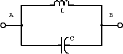
Example: An inductor and capacitor in parallel form the tank circuit shown in figure 2.5.

Figure 2.5: Tank circuit with inductor and capacitor.
- Determine an expression for the impedance of this circuit.
The impedance of an inductor and a capacitor are

Combining the impedances in parallel gives

- What is the impedance when
?
Substituting this value for
into the above result gives

Example: The tank circuit schematic shown in figure 2.6 results from the use of a real inductor.

Figure 2.6: Tank circuit with real inductor
- Find an expression for the impedance of this circuit.
The impedance of an inductor, capacitor and resistor are

The resistor and inductor are in series and this combination of impedance is in parallel with the capacitor. Combining the impedances gives

- If L=1H,
, and
F, what is the impedance when
?
Substituting this value for
into the above equation gives

Substituting the numerical values for the inductance, resistance and capacitance gives

- What is the impedance when
is very small?

- What is the phase angle between the voltage
and
at resonance and at
rad/s?
Rationalizing the denominator of the impedance gives

Taking the real and imaginary components gives


The inverse tangent of the ratio of the imaginary to real parts is

There is a resonance at

and hence

At
rad/s.
