/* Color sensor |
|
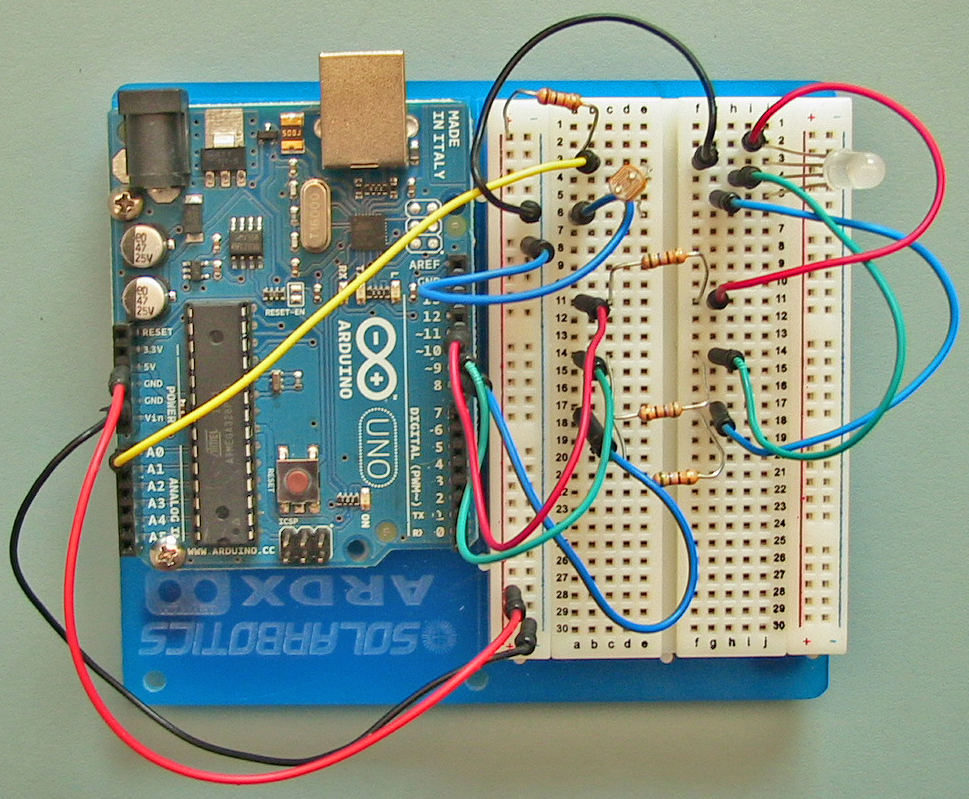
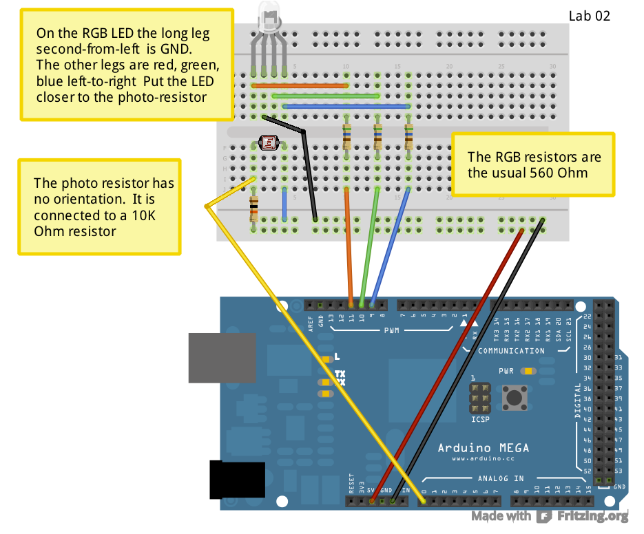
A RGB LED has three LEDs inside one package. By varying |
the intensity of each LED you can mix these primary |
colors and generate a wide range of different hues and |
saturation. |
|
The intensity of a LED is controlled by turning it off and |
on at a variable duty cycle using the analogOutput property |
of the digital output pins. |
|
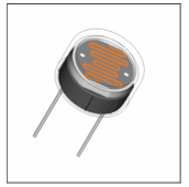
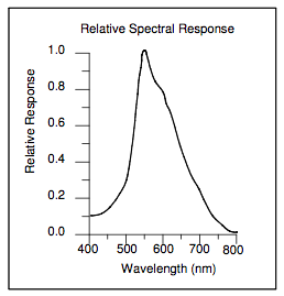
A photoresistor is a device whose resistance varies with |
the intensity of the light falling on it. As the light |
gets stronger the resistance decreases. Thus you can measure |
the amount of light falling on the photoresistor. |
|
If the illumination on a surface is of a particular color, |
then the photoresistor can be used to sense how well that |
color is reflected or absorbed by the surface. And thus |
we can detect the color. |
|
*/ |
|
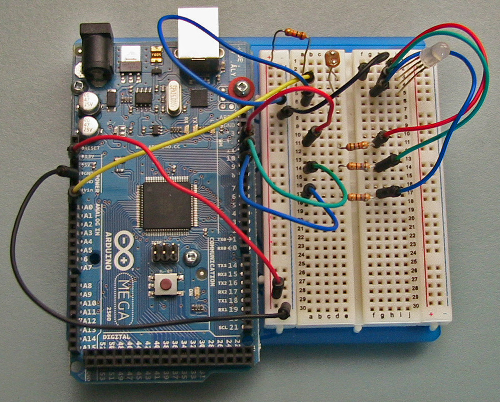
int SensorPin = 0; |
int RedPin = 11; |
int GreenPin = 10; |
int BluePin = 9; |
|
/* The senseColor function sets the LED to a particular |
mix of red, green, and blue, and then senses the intensity |
of the light falling on the photoresistor. The sampleDelay |
parameter is the number of milliseconds to wait after turning |
on the LED before sensing the intensity. It takes a while |
for the photoresistor to react, so a delay of 1 second is |
appropriate. |
|
So that the value returned by this function increases as |
a function of increasing intensity, we subtract the voltage |
read from the sensor from 1024. |
|
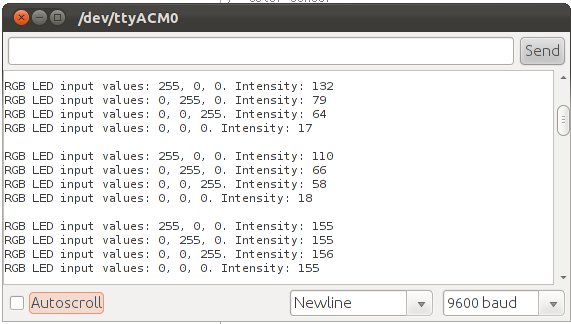
NOTE: this function also displays the values read on the |
serial monitor using the printMeasurement procedure. |
|
*/ |
|
int senseColor( |
int redOut, int greenOut, int blueOut, int sampleDelay) |
{ |
int intensity; |
|
// illuminate the surface with three colors |
|
analogWrite(RedPin, redOut); |
analogWrite(GreenPin, greenOut); |
analogWrite(BluePin, blueOut); |
|
// wait for the sensor to respond |
delay(sampleDelay); |
|
// return the intensity. A lower level means a brighter |
// illumination, so rescale |
|
intensity = 1024 - analogRead(SensorPin); |
|
printMeasurement(redOut, greenOut, blueOut, intensity); |
|
return intensity; |
} |
|
/* The printMeasurement procedure uses the serial monitor |
to print the red, green, blue values set for the LED and |
the measured intensity. |
*/ |
|
void printMeasurement(int red, int green, int blue, |
int intensity) { |
Serial.print("RGB LED input values: "); |
Serial.print(red, DEC); |
Serial.print(", "); |
Serial.print(green, DEC); |
Serial.print(", "); |
Serial.print(blue, DEC); |
Serial.print(". Intensity: "); |
Serial.println(intensity, DEC); |
} |
|
void setup() { |
pinMode(RedPin, OUTPUT); |
pinMode(GreenPin, OUTPUT); |
pinMode(BluePin, OUTPUT); |
|
Serial.begin(9600); |
} |
|
void loop() { |
int redIn; |
int greenIn; |
int blueIn; |
int blackIn; |
|
int sampleDelay = 1000; |
|
redIn = senseColor(255, 0, 0, sampleDelay); |
greenIn = senseColor(0, 255, 0, sampleDelay); |
blueIn = senseColor(0, 0, 255, sampleDelay); |
|
blackIn = senseColor(0, 0, 0, sampleDelay); |
|
Serial.println(" "); |
delay(2000); |
} |