A simple transistor model is given by ![]() .
A more general model capable of describing the family of
characteristic curves is given by
.
A more general model capable of describing the family of
characteristic curves is given by
![]()
where ![]() is a transistor-dependent function.
is a transistor-dependent function.
For AC analysis only time changes are important and we may write
![]()
where the partial derivatives are evaluated at a particular
![]() and
and ![]() - the operating point.
- the operating point.
![]() is the
forward current transfer ratio and describes the vertical spacing
is the
forward current transfer ratio and describes the vertical spacing
![]() between the curves.
The output admittance (inverse resistance) is
between the curves.
The output admittance (inverse resistance) is ![]() and describes the slope
and describes the slope ![]() of one of the curves as it passes through the
operating point.
of one of the curves as it passes through the
operating point.
Using these definitions we may write
![]()
The input signal ![]() is also related to
is also related to ![]() and
and ![]() , and
a similar argument to the above gives
, and
a similar argument to the above gives
![]()
where ![]() is the input impedance and
is the input impedance and ![]() is the reverse
voltage ratio.
is the reverse
voltage ratio.
The differential equations are linear only in the limit of small AC
signals, where the h parameters are effectively constant.
The h parameters are in general functions of the variables ![]() and
and
![]() .
We arbitrarily picked
.
We arbitrarily picked ![]() and
and ![]() as our independent variables.
We could have picked any two of
as our independent variables.
We could have picked any two of ![]() and
and ![]() .
Because the current and voltage variables are mixed the h parameters
are known as hybrid parameters.
.
Because the current and voltage variables are mixed the h parameters
are known as hybrid parameters.
In general the current and voltage signals will have both DC and AC components. The time derivatives involve only the AC component and if we restrict ourselves to sinusoidal AC signals, we may replace the time derivatives by the signals themselves (using complex notation). Our hybrid equations become
![]()
The hybrid parameters are often used as the manufacturer's specification of a transistor, but there are large variations between samples. Thus one should use the actual measured parameters in any detailed calculation based on this model. Table 5.2 shows typical values for the hybrid parameters.
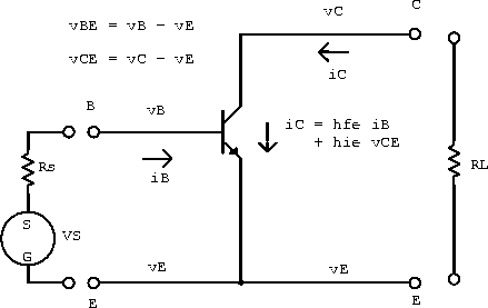
The relationship between the voltages and currents for a transistor in the common emitter configuration is shown in figure 5.6.

Figure 5.6: Transistor in the common emitter configuration.
We now make a few approximations to our hybrid parameter model to get an intuitive feel for how transistors behave in circuits. The voltage across the load resistor is
![]()
Substituting this into our first hybrid equation gives
![]()
If ![]() (good to about 10%) we can write
(good to about 10%) we can write
![]()
which is the AC equivalent of ![]() .
Similarly, using the second hybrid equation gives
.
Similarly, using the second hybrid equation gives
![]()
If ![]() (good to about 10%) we have
(good to about 10%) we have
![]()
which is the AC voltage gain.