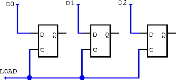
Figure 7.26: A data register using the clocked inputs to D-type flip-flops.
The circuit shown in figure 7.26 uses the clocked inputs of D flip-flops to load data into the register on the rising edge of a LOAD pulse.

Figure 7.26: A data register using the clocked inputs to
D-type flip-flops.
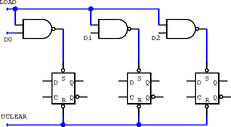
It is also possible to load data and still leave the clock inputs free (figure 7.27). The loading process requires a two-step sequence. First the register must be cleared, then it can be loaded.

Figure 7.27: A more complicated data-loading technique
leaves the clocked inputs free but requires a clear-load pulse sequence.