The topics discussed in this section are:
Protocols are sets of rules for message formats and procedures that allow machines and application programs to exchange information. These rules must be followed by each machine involved in the communication in order for the receiving host to be able to understand the message.
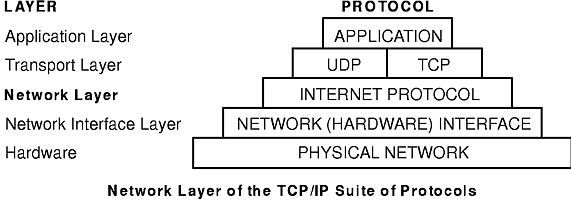
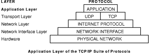
The TCP/IP suite of protocols (see figure) can be understood in terms of layers (or levels).
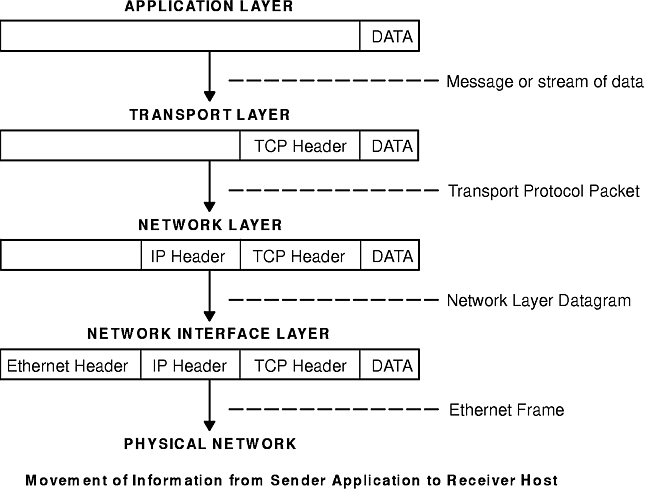
TCP/IP carefully defines how information moves from sender to receiver. First, application programs send messages or streams of data to one of the Internet Transport Layer Protocols, either the User Datagram Protocol (UDP) or the Transmission Control Protocol (TCP). These protocols receive the data from the application, divide it into smaller pieces called packets, add a destination address, and then pass the packets along to the next protocol layer, the Internet Network layer.
The Internet Network layer encloses the packet in an Internet Protocol (IP) datagram, puts in the datagram header and trailer, decides where to send the datagram (either directly to a destination or else to a gateway), and passes the datagram on to the Network Interface layer.
The Network Interface layer accepts IP datagrams and transmits them as frames over a specific network hardware, such as Ethernet or Token-Ring networks (see figure).
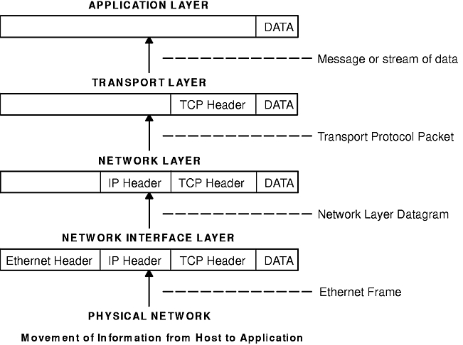
Frames received by a host go through the protocol layers in reverse. Each layer strips off the corresponding header information, until the data is back at the application layer (see figure). Frames are received by the Network Interface layer (in this case, an Ethernet adapter). The Network Interface layer strips off the Ethernet header, and sends the datagram up to the Network layer. In the Network layer, the Internet Protocol strips off the IP header and sends the packet up to the Transport layer. In the Transport layer, the Transmission Control Protocol (in this case) strips off the TCP header and sends the data up to the Application layer.
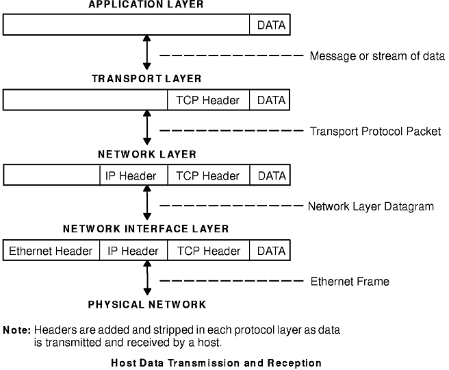
Since hosts on a network both send and receive information simultaneously, the "Host Data Transmission and Reception" figure more accurately represents a host as it communicates.
Internet Protocol (IP) Version 6 (IPv6 or IPng) is the next generation of the Internet Protocol and has been designed to be an evolutionary step from IP Version 4 (IPv4). While IPv4 has allowed the development of a global Internet, it is not capable of carrying much farther into the future because of two fundamental factors: limited address space and routing complexity. IPv4's 32-bit addresses do not provide enough flexibility for global Internet routing. The deployment of Classless InterDomain Routing (CIDR) has extended the lifetime of IPv4 routing by a number of years, but the effort to manage the routing, however, continues to increase. Even if IPv4 routing could be scaled up, the Internet will eventually run out of network numbers.
The Internet Engineering Task Force (IETF) recognized that IPv4 would not be able to support the phenomenal growth of the Internet, so the IETF IPng working group was formed. Of the proposals that were made, Simple Internet Protocol Plus (SIPP) was chosen as an evolutionary step in the development of IP. This was renamed to IPng, and RFC1883 was finalized in December of 1995.
IPv6 extends the maximum number of Internet addresses to handle the ever increasing Internet user population. As an evolutionary change from IPv4, IPv6 has the advantage of allowing the new and the old to coexist on the same network. This coexistence enables an orderly migration from IPv4 (32 bit addressing) to IPv6 (128 bit addressing) on an operational network.
This overview is intended to give the reader a general understanding of the IPng protocol. For detailed information, please refer to RFCs 1883, 1884, 1885, 1886, 1970, 1971, and 2133.
IPv6 increases the IP address size from 32 bits to 128 bits, thereby supporting more levels of addressing hierarchy, a much greater number of addressable nodes, and simpler autoconfiguration of addresses.
In IPv6, there are three types of addresses:
| unicast | A packet sent to a unicast address is delivered to the interface identified by that address. A unicast address has a particular scope: link-local, site-local, global. There are also two special unicast addresses:
In IPv6, this is only one address, not an entire network. |
| multicast | A packet sent to a multicast address is delivered to all interfaces identified by that address. A multicast address is identified by the prefix ff::/8. As with unicast addresses, multicast addresses have a similar scope: node-local, link-local, site-local, and organization-local. |
| anycast | An anycast address is an address that has a single sender, multiple listeners, and only one responder (normally the "nearest" one, according to the routing protocols' measure of distance). An example may be several web servers listening on an anycast address. When a request is sent to the anycast address, only one responds.
An anycast address is indistinguishable from a unicast address. A unicast address becomes an anycast address when more than one interface is configured with that address. |
Note: There are no broadcast addresses in IPv6. Their function has been superseded by the multicast address.
The primary mechanisms available that enable a node to boot up and start communicating with other nodes over an IPv4 network are hard-coding, BOOTP, and DHCP. These work fairly well, but each has its own difficulties: hard-coding makes renumbering inordinately difficult; BOOTP and DHCP require that the host broadcast and are dependent on a remote server.
IPv6 introduces the concept of scope to IP addresses, one of which is link-local. This allows a host to construct a valid address from the predefined link-local prefix and its local identifier, which is typically the medium access control (MAC) address of the interface to be configured. Using this address, the node can multicast to a server, rather than broadcast and, for a fully-isolated subnet, may not need any other address configuration.
With IPv4, the only generally recognizable meaning in addresses are broadcast (typically all 1 or all 0), and classes (for example, a class D is multicast). With IPv6, the prefix can be quickly examined to determine scope (for example, link-local), multicast versus unicast, and a mechanism of assignment (provider-based, geography-based, etc.).
Routing information may be explicitly loaded into the upper bits of addresses as well, but this has not yet been finalized by the IETF (for provider-based addresses, routing information is implicitly present in the address).
When an interface is initialized or reinitialized, it uses autoconfiguration to tentatively associate a link-local address with that interface (the address is not yet assigned to that interface in the traditional sense). At this point, the interface joins the all-nodes and solicited-nodes multicast groups, and sends a neighbor discovery message to these groups. By using the multicast address, the node can determine whether that particular link-local address has been previously assigned, and choose an alternate address. This reduces a common error in network management, namely assigning the same address to two different interfaces on the same link. (It is still possible to create duplicate global-scope addresses for nodes that are not on the same link.)
Neighbor Discovery (ND) protocol for IPv6 is used by nodes (hosts and routers) to determine the link-layer addresses for neighbors known to reside on attached links, and maintain per-destination routing tables for active connections. Hosts also use Neighbor Discovery to find neighboring routers that are willing to forward packets on their behalf and detect changed link-layer addresses. Neighbor Discovery Protocol (NDP) uses the Internet Control Message Protocol (ICMP) Version 6 with its own unique message types. In general terms, the IPv6 Neighbor Discovery protocol corresponds to a combination of the IPv4 Address Resolution Protocol (ARP), ICMP Router Discovery (RDISC), and ICMP Redirect (ICMPv4), but with many improvements over these IPv4 protocols.
IPv6 defines both a stateful and stateless address autoconfiguration mechanism. Stateless autoconfiguration requires no manual configuration of hosts; minimal, if any, configuration of routers; and no additional servers. The stateless mechanism allows a host to generate its own addresses using a combination of locally available information and information advertised by routers. Routers advertise prefixes that identify the subnets associated with a link, while hosts generate an interface token that uniquely identifies an interface on a subnet. An address is formed by combining the two. In the absence of routers, a host can only generate link-local addresses. However, link-local addresses are sufficient for allowing communication among nodes attached to the same link.
To simplify routing issues, IPv6 addresses are considered in two parts: a prefix and an ID. This may seem no different from the IPv4 net-host address breakdown, but it has two advantages:
| no class | No fixed number of bits for prefix or ID, which allows for a reduction in loss due to over-allocation |
| nesting | An arbitrary number of divisions can be employed by considering different numbers of bits as the prefix. |
Case 1:
________________________________________________________________________________________________________
|                                                                                                      |
|                                            128 bits                                                  |
|                                                                                                      |
|______________________________________________________________________________________________________|
|                                                                                                      |
|                                          Node address                                                |
|                                                                                                      |
|______________________________________________________________________________________________________|
Case 2:
________________________________________________________________________________________________________
|                                                                       |                              |
|                         n bits                                        |         128-n bits           |
|                                                                       |                              |
________________________________________________________________________|______________________________|
|                                                                       |                              |
|                      Subnet prefix                                    |        Interface ID          |
|                                                                       |                              |
|_______________________________________________________________________|______________________________|
Case 3:
________________________________________________________________________________________________________
|                                                  |                         |                         |
|                 n bits                           |        80-n bits        |          48 bits        |
|                                                  |                         |                         |
|__________________________________________________|_________________________|_________________________|
|                                                  |                         |                         |
|              Subscriber prefix                   |        Subnet ID        |        Interface ID     |
|                                                  |                         |                         |
|__________________________________________________|_________________________|_________________________|
Case 4:
________________________________________________________________________________________________________
|                        |                         |                         |                         |
|        s bits          |         n bits          |         m bits          |      128-s-n-m bits     |
|                        |                         |                         |                         |
|________________________|_________________________|_________________________|_________________________|
|                        |                         |                         |                         |
|   Subscriber prefix    |        Area ID          |       Subnet ID         |       Interface ID      |
|                        |                         |                         |                         |
|________________________|_________________________|_________________________|_________________________|
Generally, IPv4 cannot go beyond Case 3, even with VLSM. (This is as much an artifact of the shorter address length as the definition of variable length prefixes, but is worth noting nonetheless).
IPv6 simplifies the IP header, either by removing entirely or by moving to an extension header, some of the fields found in the IPv4 header and it defines a more flexible format for optional information (the extension headers). Specifically, note the absence of:
IPv4 Header:
_________________________________________________________________________________________________________
|                   |                    |                    |                                         |
|      Version      |        IHL         |  Type of Service   |              Total Length               |
|                   |                    |                    |                                         |
|___________________|____________________|____________________|_________________________________________|
|                                                             |                    |                    |
|                       Identification                        |        Flags       |  Fragment Offset   |
|                                                             |                    |                    |
|_____________________________________________________________|____________________|____________________|
|                                        |                    |                                         |
|              Time to Live              |      Protocol      |             Header Checksum             |
|                                        |                    |                                         |
|________________________________________|____________________|_________________________________________|
|                                                                                                       |
|                                            Source Address                                             |
|                                                                                                       |
|_______________________________________________________________________________________________________|
|                                                                                                       |
|                                         Destination Address                                           |
|                                                                                                       |
|_______________________________________________________________________________________________________|
|                                                                                  |                    |
|                                 Options                                          |      Padding       |
|                                                                                  |                    |
|__________________________________________________________________________________|____________________|
IPv6 Header:
_________________________________________________________________________________________________________
|                   |                    |                                                              |
|      Version      |       Prio         |                        Flow Label                            |
|                   |                    |                                                              |
|___________________|____________________|______________________________________________________________|
|                                                             |                    |                    |
|                      Payload Length                         |    Next Header     |     Hop Limit      |
|                                                             |                    |                    |
|_____________________________________________________________|____________________|____________________|
|                                                                                                       |
|                                            Source Address                                             |
|                                                                                                       |
|_______________________________________________________________________________________________________|
|                                                                                                       |
|                                         Destination Address                                           |
|                                                                                                       |
|_______________________________________________________________________________________________________|
IPng includes an improved options mechanism over IPv4. IPv6 options are placed in separate extension headers that are located between the IPv6 header and the transport-layer header in a packet. Most extension headers are not examined or processed by any router along a packet's delivery path until it arrives at its final destination. This mechanism facilitates a major improvement in router performance for packets containing options. In IPv4 the presence of any options requires the router to examine all options.
Another improvement is that, unlike IPv4 options, IPv6 extension headers can be of arbitrary length and the total amount of options carried in a packet is not limited to 40 bytes. This feature, plus the manner in which it is processed, permits IPv6 options to be used for functions that were not practical in IPv4, such as the IPv6 Authentication and Security Encapsulation options.
To improve the performance when handling subsequent option headers and the transport protocol which follows, IPv6 options are always an integer multiple of eight octets long to retain this alignment for subsequent headers.
By using extension headers instead of a protocol specifier and options fields, newly defined extensions can be integrated more easily.
Current specifications define extension headers in the following ways:
While quality of service can be controlled by use of a control protocol such as RSVP, IPv6 provides for explicit priority definition for packets by using the priority field in the IP header. A node can set this value to indicate the relative priority of a particular packet or set of packets, which can then be used by the node, one or more routers, or the destination to make choices concerning the packet (that is, dropping it or not).
IPv6 specifies two types of priorities, those for congestion-controlled traffic, and those for non-congestion-controlled traffic. No relative ordering is implied between the two types.
Congestion-controlled traffic is defined as traffic that responds to congestion through some sort of "back-off" or other limiting algorithm. Priorities for congestion-controlled traffic are:
| 0 | uncharacterized traffic |
| 1 | "filler" traffic (for example, netnews) |
| 2 | unattended data transfer (for example, electronic mail) |
| 3 | (reserved) |
| 4 | attended bulk transfer (for example, FTP) |
| 5 | (reserved) |
| 6 | interactive traffic (for example, Telnet) |
| 7 | control traffic (for example, routing protocols) |
Non-congestion-controlled traffic is defined as traffic that responds to congestion by dropping (or simply not resending) packets, such as video, audio, or other real-time traffic. Explicit levels are not defined with examples, but the ordering is similar to that for congestion-controlled traffic:
This priority control is only applicable to traffic from a particular source address. Control traffic from one address is not an explicitly higher priority than attended bulk transfer from another address.
Outside of basic prioritization of traffic, IPv6 defines a mechanism for specifying a particular flow of packets. In IPv6 terms, a flow is defined as "a sequence of packets sent from a particular source to a particular (unicast or multicast) destination for which the source desires special handling by the intervening routers."
This flow identification may be used for priority control, but may also be used for any number of other controls.
The flow label is chosen randomly, and should not be construed as identifying any characteristic of the traffic other than the flow to which it belongs. This means that a router cannot determine that a packet is a particular type (for example, FTP) by examining the flow label. It will, however, be able to determine that it is part of the same sequence of packets as the last packet containing that label.
Note: In AIX 4.3 and until IPv6 is in general use, the flow label is mostly experimental. Uses and controls involving flow labels have not yet been defined nor standardized.
An IPv4 packet size is limited to 64K. Using the jumbo payload extension header, an IPv6 packet can be up to 232 octets (slightly over 4 gigabytes).
The key to a successful IPv6 transition is compatibility with the existing installed base of IPv4 hosts and routers. Maintaining compatibility with IPv4 while deploying IPv6 streamlines the task of transitioning the Internet to IPv6.
In most cases, the IPv6 routing infrastructure will evolve over time. While the IPv6 infrastructure is being deployed, the existing IPv4 routing infrastructure can remain functional, and can be used to carry IPv6 traffic. Tunneling provides a way to use an existing IPv4 routing infrastructure to carry IPv6 traffic.
IPv6/IPv4 hosts and routers can tunnel IPv6 datagrams over regions of IPv4 routing topology by encapsulating them within IPv4 packets. Tunneling can be used in a variety of ways:
| Router-to-Router | IPv6/IPv4 routers interconnected by an IPv4 infrastructure can tunnel IPv6 packets between themselves. In this case, the tunnel spans one segment of the end-to-end path that the IPv6 packet takes. |
| Host-to-Router | IPv6/IPv4 hosts can tunnel IPv6 packets to an intermediary IPv6/IPv4 router that is reachable through an IPv4 infrastructure. This type of tunnel spans the first segment of the packet's end-to-end path. |
| Host-to-Host | IPv6/IPv4 hosts that are interconnected by an IPv4 infrastructure can tunnel IPv6 packets between themselves. In this case, the tunnel spans the entire end-to-end path that the packet takes. |
| Router-to-Host | IPv6/IPv4 routers can tunnel IPv6 packets to their final destination IPv6/IPv4 host. This tunnel spans only the last segment of the end-to-end path. |
Tunneling techniques are usually classified according to the mechanism by which the encapsulating node determines the address of the node at the end of the tunnel. In router-to-router or host-to-router methods, the IPv6 packet is being tunneled to a router. In host-to-host or router-to-host methods, the IPv6 packet is tunneled all the way to its final destination.
The entry node of the tunnel (the encapsulating node) creates an encapsulating IPv4 header and transmits the encapsulated packet. The exit node of the tunnel (the decapsulating node) receives the encapsulated packet, removes the IPv4 header, updates the IPv6 header, and processes the received IPv6 packet. However, the encapsulating node needs to maintain soft state information for each tunnel, such as the maximum transmission unit (MTU) of the tunnel, to process IPv6 packets forwarded into the tunnel.
For details about IP Security, versions 4 and 6, see Chapter 4. Internet Protocol (IP) Security.
A host can have more than one interface defined. A host with two or more active interfaces is called multihomed. Each interface has a link local address associated with it. Link local addresses are sufficient for allowing communication among nodes attached to the same link.
A multihomed host will have two or more associated link local addresses. In AIX's IPv6 implementation, there are 4 options to handling how link-layer address resolution is resolved on multihomed hosts. Option 1 is turned on by default.
| Option 0 | No multihomed actions are taken. Transmits will go out on the first link local interface. When the Neighbor Discovery Protocol must perform address resolution, it multicasts a Neighbor Solicitation message out on each interface with a link local address defined. NDP queues the data packet until the first Neighbor Advertisement message is received. The data packet is then sent out on this link. |
| Option 1 | When the Neighbor Discovery Protocol must perform address resolution (i.e., when sending a data packet to a destination and the the link-layer information for the next-hop is not in the Neighbor Cache), it multicasts a Neighbor Solicitation message out on each interface with a link local address defined. NDP then queues the data packet until it gets the link-layer information. NDP then waits until a response is received for each interface. This guarantees that the data packets are sent on the appropriate outgoing interfaces. If NDP did not wait, but responded to the first Neighbor Advertisement received, it would be possible for a data packet to be sent out on a link not associated with the packet's source address. Because NDP must wait, a delay in the first packet being sent will occur. However, the delay will have occurred anyway in waiting for the first response. |
| Option 2 | Multihomed operation is allowed, but dispatching of a data packet is limited to the interface specified by main_if6. When the Neighbor Discovery Protocol must perform address resolution, it multicasts a Neighbor Solicitation message out on each interface with a link local address defined. It then waits for a Neighbor Advertisement message from the interface specified by main_if6 (see the no command). Upon receiving a response from this interface, the data packet is sent out on this link. |
| Option 3 | Multihomed operation is allowed, but dispatching of a data packet is limited to the interface specified by main_if6 and site local addresses will only be routed for the interface specified by main_site6 (see the no command). The Neighbor Discovery Protocol will operate just as it does for Option 2. For applications that route data packets using site local addresses, on a multihomed host only the site local address specified by main_site6 will be used. |
Packet tracing is the process by which you can verify the path of a packet through the layers to its destination. The iptrace command performs network interface level packet tracing. The ipreport command issues output on the packet trace in both hexadecimal and ASCII format. The trpt command performs transport protocol level packet tracking for the TCP. The trpt command output is more detailed, including information on time, TCP state, and packet sequencing.
At the Network Interface layer, packet headers are attached to outgoing data (see figure). Packets are then sent through the network adapter to the appropriate network. Packets may pass through many gateways before reaching their destinations. At the destination network, the headers are stripped from the packets and the data is sent to the appropriate host.
Packet header information for several of the more common network interfaces follows.
The following table represents an Internet Protocol (IP) or Address Resolution Protocol (ARP) frame header for the Ethernet adapter.
| Ethernet Adapter Frame Header | ||
| Field | Length | Definition |
| DA | 6 bytes | Destination address. |
| SA | 6 bytes | Source address. If bit 0 of this field is set to 1, it indicates that routing information (RI) is present. |
| Type | 2 bytes | Specifies whether the packet is IP or ARP. The type number values are listed below. |
| IP | 0800 |
| ARP | 0806 |
The medium access control (MAC) header for the token-ring adapter is composed of five fields, as shown in the following table.
| Token-Ring MAC Header | ||
| Field | Length | Definition |
| AC | 1 byte | Access control. The value in this field x`00' gives the header priority 0. |
| FC | 1 byte | Field control. The value in this field x`40' specifies the Logical Link Control frame. |
| DA | 6 bytes | Destination address. |
| SA | 6 bytes | Source address. If bit 0 of this field is set to 1, it indicates that routing information (RI) is present. |
| RI | 18 bytes | Routing information. The valid fields are discussed below. |
The MAC header consists of two routing information fields of 2 bytes each: routing control (RC) and segment numbers. A maximum of eight segment numbers may be used to specify recipients of a limited broadcast. RC information is contained in bytes 0 and 1 of the RI field. The settings of the first two bits of the RC field have the following meanings:
The logical link control (LLC) header is composed of five fields, as shown in the following LLC header table.
| 802.3 LLC Header | ||
| Field | Length | Definition |
| DSAP | 1 byte | Destination service access point. The value in this field is x`aa'. |
| SSAP | 1 byte | Source service access point. The value in this field is x`aa'. |
| CONTROL | 1 byte | Determines the LLC commands and responses. The three possible values for this field are discussed below. |
| PROT_ID | 3 bytes | Protocol ID. This field is reserved. It has a value of x`0'. |
| TYPE | 2 bytes | Specifies whether the packet is IP or ARP. |
The MAC header for the 802.3 adapter is composed of three fields, as shown in the following MAC header table.
| 802.3 MAC Header | ||
| Field | Length | Definition |
| DA | 6 bytes | Destination address. |
| SA | 6 bytes | Source address. If bit 0 of this field is set to 1, it indicates that routing information (RI) is present. |
The LLC header for 802.3 is the same as for Token-Ring MAC header.
The Internet network-level protocols handle machine-to-machine communication. In other words, this layer implements TCP/IP routing. These protocols accept requests to send packets (along with the network address of the destination machine) from the Transport layer, convert the packets to datagram format, and send them down to the Network Interface layer for further processing (see figure).
TCP/IP provides the protocols that are required to comply with RFC 1100, Official Internet Protocols, as well as other protocols commonly used by hosts in the Internet community.
Note: The use of Internet network, version, socket, service, and protocol numbers in TCP/IP also complies with RFC 1010, Assigned Numbers.
The first network-level protocol is the Address Resolution Protocol (ARP). ARP dynamically translates Internet addresses into the unique hardware addresses on local area networks.
To illustrate how ARP works, consider two nodes, jim and fred. If node jim wishes to communicate with fred, and jim and fred are on different local area networks (LANs), jim and fred communicate through bridges, routers, or gateways, using IP addresses. If, on the other hand, jim and fred are on the same LAN, an IP address alone is insufficient for direct communication. Within a LAN, nodes communicate using low-level hardware addresses.
Nodes on the same segment of the same LAN use ARP to determine the hardware address of other nodes. First, node jim broadcasts an ARP request for node fred's hardware address. The ARP request contains jim's IP and hardware addresses, and fred's IP address. When fred receives the ARP request, it places an entry for jim in its ARP cache (which is used to map quickly from IP address to hardware address), then responds directly to jim with an ARP response containing fred's IP and hardware addresses. When node jim receives fred's ARP response, it places an entry for fred in its ARP cache.
Once an ARP cache entry exists at jim for fred, node jim is able to send packets directly to fred without resorting again to ARP (unless the ARP-cache entry for fred is deleted, in which case ARP is reused to contact fred).
Unlike most protocols, ARP packets do not have fixed-format headers. Instead, the message is designed to be useful with a variety of network technologies, such as:
However, ARP does not translate addresses for Serial Line Interface Protocol (SLIP) or Serial Optical Channel Converter, since these are point-to-point connections.
The kernel maintains the translation tables, and the ARP is not directly available to users or applications. When an application sends an Internet packet to one of the interface drivers, the driver requests the appropriate address mapping. If the mapping is not in the table, an ARP broadcast packet is sent through the requesting interface driver to the hosts on the local area network.
Entries in the ARP mapping table are deleted after 20 minutes; incomplete entries are deleted after 3 minutes. To make a permanent entry in the ARP mapping tables, use the arp command with the pub parameter:
arp -s 802.3 host2 0:dd:0:a:8s:0 pub
When any host that supports ARP receives an ARP request packet, the host notes the IP and hardware addresses of the requesting system and updates its mapping table, if necessary. If the receiving host IP address does not match the requested address, the host discards the request packet. If the IP address does match, the receiving host sends a response packet to the requesting system. The requesting system stores the new mapping and uses it to transmit any similar pending Internet packets.
The second network-level protocol is the Internet Control Message Protocol (ICMP). ICMP is a required part of every Internet Protocol implementation. ICMP handles error and control messages for IP. This protocol allows gateways and hosts to send problem reports to the machine sending a packet. ICMP does the following:
Note: ICMP uses the basic support of IP as if it were a higher-level protocol. However, ICMP is actually an integral part of IP and must be implemented by every IP module.
ICMP provides feedback about problems in the communications environment, but does not make IP reliable. That is, ICMP does not guarantee that an IP packet is delivered reliably or that an ICMP message is returned to the source host when an IP packet is not delivered or is incorrectly delivered.
ICMP messages may be sent in any of the following situations:
TCP/IP sends and receives several ICMP message types. ICMP is embedded in the kernel, and no application programming interface (API) is provided to this protocol.
ICMP sends and receives the following message types:
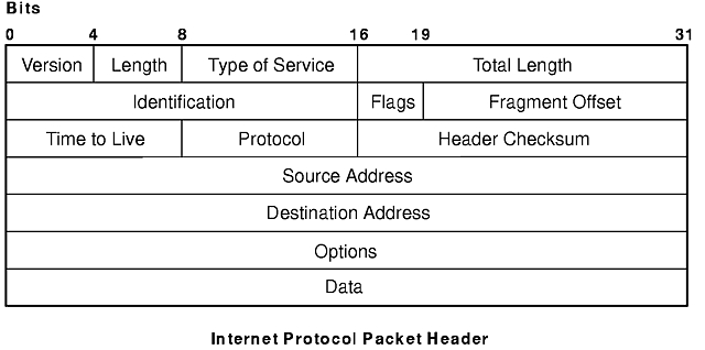
The third network-level protocol is the Internet Protocol (IP), which provides unreliable, connectionless packet delivery for the Internet. IP is connectionless because it treats each packet of information independently. It is unreliable because it does not guarantee delivery (that is, it does not require acknowledgments from the sending host, the receiving host, or intermediate hosts).
IP provides the interface to the network interface level protocols. The physical connections of a network transfer information in a frame with a header and data. The header contains the source address and the destination address. IP uses an Internet datagram, which contains information similar to the physical frame. The datagram also has a header containing Internet addresses of both source and destination of the data.
IP defines the format of all the data sent over the Internet (see figure).
Outgoing packets automatically have an IP header prefixed to them, and incoming packets have their IP header removed before being sent to the higher-level protocols. The IP protocol provides for the universal addressing of hosts in the Internet network.
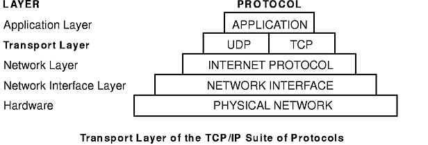
The TCP/IP transport-level protocols (see figure) allow application programs to communicate with other application programs. User Datagram Protocol (UDP) and the TCP are the basic transport-level protocols for making connections between Internet hosts. Both TCP and UDP allow programs to send messages to and receive messages from applications on other hosts. When an application sends a request to the Transport layer to send a message, UDP and TCP break the information into packets, add a packet header including the destination address, and send the information to the Network layer for further processing. Both TCP and UDP use protocol ports on the host to identify the specific destination of the message.
Higher-level protocols and applications use UDP to make datagram connections and TCP to make stream connections. The operating system sockets interface implements these protocols.
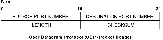
Sometimes an application on a network needs to send messages to a specific application or process on another network. The UDP provides a datagram means of communication between applications on Internet hosts. Because senders do not know which processes are active at any given moment, UDP uses destination protocol ports (or abstract destination points within a machine), identified by positive integers, to send messages to one of multiple destinations on a host. The protocol ports receive and hold messages in queues until applications on the receiving network can retrieve them.
Since UDP relies on the underlying IP to send its datagrams, UDP provides the same connectionless message delivery as IP. It offers no assurance of datagram delivery or duplication protection. However, UDP does allow the sender to specify source and destination port numbers for the message and calculates a checksum of both the data and header. These two features allow the sending and receiving applications to ensure the correct delivery of a message (see figure). Applications that require reliable delivery of datagrams must implement their own reliability checks when using UDP. Applications that require reliable delivery of streams of data should use TCP.
The applications programming interface (API) to UDP is a set of library subroutines provided by the sockets interface.
TCP provides reliable stream delivery of data between Internet hosts. Like UPD, TCP uses Internet Protocol, the underlying protocol, to transport datagrams, and supports the block transmission of a continuous stream of datagrams between process ports. Unlike UDP, TCP provides reliable message delivery. TCP ensures that data is not damaged, lost, duplicated, or delivered out of order to a receiving process. This assurance of transport reliability keeps applications programmers from having to build communications safeguards into their software.
The following are operational characteristics of TCP:
The TCP Packet Header figure illustrates these characteristics.
The applications programming interface to TCP consists of a set of library subroutines provided by the sockets interface.
TCP/IP implements higher-level Internet protocols at the application program level (see figure). When an application needs to send data to another application on another host, the applications send the information down to the transport level protocols to prepare the information for transmission.
The official Internet application-level protocols include:
TCP/IP implements other higher-level protocols that are not official Internet protocols but are commonly used in the Internet community at the application program level. These protocols include:
TCP/IP does not provide APIs to any of these application-level protocols.
The Domain Name Protocol (DOMAIN) allows a host in a domain to act as a name server for other hosts within the domain. DOMAIN uses UDP or TCP as its underlying protocol and allows a local network to assign host names within its domain independently from other domains. Normally, the DOMAIN protocol uses UDP. However, if the UDP response is truncated, TCP may be used. The DOMAIN protocol in TCP/IP supports both.
In the Domain hierarchical naming system, local resolver routines may resolve Internet names and addresses using a local name resolution database maintained by the named daemon. If the name requested by the host is not in the local database, the resolver routine queries a remote DOMAIN name server. In either case, if the name resolution information is unavailable, the resolver routines attempt to use the /etc/hosts file for name resolution.
Note: TCP/IP configures local resolver routines for the DOMAIN protocol if the local file /etc/resolv.conf exists. If this file does not exist, the TCP/IP configures the local resolver routines to use the /etc/hosts database.
TCP/IP implements the DOMAIN protocol in the named daemon and in the resolver routines and does not provide an API to this protocol.
Exterior Gateway Protocol (EGP) is the mechanism that allows the exterior gateway of an autonomous system to share routing information with exterior gateways on other autonomous systems.
An autonomous system is a group of networks and gateways for which one administrative authority has responsibility. Gateways are interior neighbors if they reside on the same autonomous system and exterior neighbors if they reside on different autonomous systems. Gateways that exchange routing information using EGP are said to be EGP peers or neighbors. Autonomous system gateways use EGP to provide access information to their EGP neighbors.
EGP allows an exterior gateway to ask another exterior gateway to agree to exchange access information, continually checks to ensure that its EGP neighbors are responding, and helps EGP neighbors to exchange access information by passing routing update messages.
EGP restricts exterior gateways by allowing them to advertise only those destination networks reachable entirely within that gateway's autonomous system. Thus, an exterior gateway using EGP passes along information to its EGP neighbors but does not advertise access information about its EGP neighbors outside its autonomous system.
EGP does not interpret any of the distance metrics that appear in routing update messages from other protocols. EGP uses the distance field to specify whether a path exists (a value of 255 means that the network is unreachable). The value cannot be used to compute the shorter of two routes unless those routes are both contained within a single autonomous system. Therefore, EGP cannot be used as a routing algorithm. As a result, there will be only one path from the exterior gateway to any network.
In contrast to the Routing Information Protocol (RIP), which can be used within an autonomous system of Internet networks that dynamically reconfigure routes, EGP routes are predetermined in the /etc/gated.conf file. EGP assumes that IP is the underlying protocol.
TCP/IP implements the EGP protocol in the gated server command and does not provide an API to this protocol.
File Transfer Protocol (FTP) allows hosts to transfer data among dissimilar hosts, as well as files between two foreign hosts indirectly. FTP provides for such tasks as listing remote directories, changing the current remote directory, creating and removing remote directories, and transferring multiple files in a single request. FTP keeps the transport secure by passing user and account passwords to the foreign host. Although FTP is designed primarily to be used by applications, it also allows interactive user-oriented sessions.
FTP uses reliable stream delivery (TCP/IP) to send the files and uses a Telnet connection to transfer commands and replies. FTP also understands several basic file formats including NETASCII, IMAGE, and Local 8.
TCP/IP implements FTP in the ftp user command and the ftpd server command and does not provide an applications programming interface (API) to this protocol.
When creating anonymous ftp users and directories please be sure that the home directory for users ftp and anonymous (for example, /u/ftp) is owned by root and does not allow write permissions (for example, dr-xr-xr-x). The script /usr/samples/tcpip/anon.ftp can be used to create these accounts, files and directories.
The Telnet Protocol (TELNET) provides a standard method for terminal devices and terminal-oriented processes to interface. TELNET is commonly used by terminal emulation programs that allow you to log into a remote host. However, TELNET can also be used for terminal-to-terminal communication and interprocess communication. TELNET is also used by other protocols (for example, FTP) for establishing a protocol control channel.
TCP/IP implements TELNET in the tn, telnet, or tn3270 user commands. The telnetd daemon does not provide an API to TELNET.
TCP/IP supports the following Telnet options which are negotiated between the client and server:
Note: Telnet must allow transmission of eight bit characters when not in binary mode in order to implement ISO 8859 Latin code page. This is necessary for internationalization of the TCP/IP commands.
The Trivial File Transfer Protocol (TFTP) can read and write files to and from a foreign host. Since TFTP uses the unreliable User Datagram Protocol to transport files, it is generally quicker than FTP. Like FTP, TFTP can transfer files as either NETASCII characters or as 8-bit binary data. Unlike FTP, TFTP cannot be used to list or change directories at a foreign host and it has no provisions for security like password protection. Also, data can be written or retrieved only in public directories.
The TCP/IP implements TFTP in the tftp and utftp user commands and in the tftpd server command. The utftp command is a form of the tftp command for use in a pipe. TCP/IP does not provide an API to this protocol.
The Name/Finger Protocol (FINGER) is an application-level Internet protocol that provides an interface between the finger command and the fingerd daemon. The fingerd daemon returns information about the users currently logged in to a specified remote host. If you execute the finger command specifying a user at a particular host, you will obtain specific information about that user. The FINGER Protocol must be present at the remote host and at the requesting host. FINGER uses Transmission Control Protocol (TCP) as its underlying protocol.
Note: TCP/IP does not provide an API to this protocol.
Local-Network Protocol (HELLO) is an interior gateway protocol designed for use within autonomous systems. (For more information, see "Autonomous Systems".) HELLO maintains connectivity, routing, and time-keeping information. It allows each machine in the network to determine the shortest path to a destination based on time delay and then dynamically updates the routing information to that destination.
The gated daemon provides the Distributed Computer Network (DCN) local network protocol.
The rexec user command and the rexecd daemon provide the remote command execution protocol, allowing users to run commands on a compatible remote host.
The rlogin user command and the rlogind daemon provide the remote login protocol, allowing users to log in to a remote host and use their terminals as if they were directly connected to the remote host.
The rsh user command and the rshd daemon provide the remote command shell protocol, allowing users to open a shell on a compatible foreign host for running commands.
Routing Information Protocol (RIP) and the routed and gated daemons that implement it keep track of routing information based on gateway hops and maintain kernel-routing table entries.
The timed daemon is used to synchronize a host's time with the time of other hosts. It is based on the client/server concept.
For compatibility with the general network environment, well-known numbers are assigned for the Internet versions, networks, ports, protocols, and protocol options. Additionally, well-known names are also assigned to machines, networks, operating systems, protocols, services, and terminals. TCP/IP complies with the assigned numbers and names defined in RFC 1010, Assigned Numbers.
The Internet Protocol defines a 4-bit field in the IP header that identifies the version of the general Internetwork protocol in use. For IP, this version number in decimal is 4. For details on the assigned numbers and names used by TCP/IP, refer to the /etc/protocols and /etc/services files included with TCP/IP. For further details on the assigned numbers and names, refer to RFC 1010 and the /etc/services file.