[ Previous |
Next |
Contents |
Glossary |
Home |
Search ]
AIX Version 4.3 System Management Guide: Communications and Networks
TCP/IP Network Adapter Cards
The topics discussed in this section are:
The network adapter card is the hardware that is physically attached to the network cabling. It is responsible for receiving and transmitting data at the physical level. The network adapter card is controlled by the network adapter device driver.
A machine must have one network adapter card (or connection) for each network (not network type) to which it connects. For instance, if a host attaches to two token-ring networks, it must have two network adapter cards.
TCP/IP uses the following network adapter cards and connections:
- Standard Ethernet Version 2
- IEEE 802.3
- Token-ring
- Asynchronous adapters and native serial ports
- Fiber Distributed Data Interface (FDDI)
- Serial Optical Channel Converter
- Turboways 100 and Turboways 155 ATM
The Ethernet and 802.3 network technologies use the same type of adapter.
Each machine provides a limited number of expansion slots, some or all of which you may wish to use for communications adapters. Additionally, each machine supports a limited number of communications adapters of a given type. Each machine supports up to eight Ethernet/802.3 adapters, up to eight token-ring adapters, and one asynchronous adapter card with up to 64 connections. Within these limits (software limitations), you can install any combination of these adapters up to the total number of expansion slots available in your machine (hardware limitations).
Only one Transmission Control Protocol/Internet Protocol (TCP/IP) interface is configurable regardless of the number of Serial Optical Channel Converters supported by the system. The Serial Optical device driver makes use of both channel converters even though only one logical TCP/IP interface is configured.
Installing a Network Adapter
To install a network adapter:
- Shut down the computer. See the shutdown command for information on how to shut down a system.
- Turn off the computer's power.
- Remove the computer's cover.
- Find a free slot on the Micro Channel bus and insert the network adapter into it, being careful to seat the adapter properly.
- Replace the computer's cover.
- Restart the computer.
Configuring and Managing Adapters
To configure and manage token-ring or Ethernet adapters, use the tasks in the following table.
| Configuring and Managing Adapters Tasks |
|---|
Web-based System Manager: wsm network
fast path
(Network application)
-OR- |
| Task |
SMIT Fast Path |
Command or File |
| Configure an Adapter |
smit chgtok (token ring)
smit chgenet (Ethernet) |
- Determine adapter name:1
lsdev -C -c adapter -t tokenring -H
or
lsdev -C -c adapter -t ethernet -H
- Reset ring speed (token ring) or connector type (Ethernet), if necessary. For example:
chdev -l tok0 -a ring_speed=16 -P
or
chdev -l ent0 -a bnc_select=dix -P
|
| Determining a Network Adapter's Hardware Address |
smit chgtok (token ring)
smit chgenet (Ethernet) |
lscfg -l tok0 -v (token ring)2
lscfg -l ent0 -v (Ethernet)2 |
| Setting an Alternate Hardware Address |
smit chgtok (token ring)
smit chgenet (Ethernet) |
- Define the alternate hardware address. For example, for token ring:2,3
chdev -l tok0 -a alt_addr=0X10005A4F1B7F
For Ethernet:2,3
chdev -l ent0 -a alt_addr=0X10005A4F1B7F -p
- Begin using alternate address, for token ring:4
chdev -l tok0 -a use_alt_addr=yes
For Ethernet:4
chdev -l ent0 -a use_alt_addr=yes
|
|
|
|
Notes:
- The name of a network adapter can change if you move it from one slot to another or remove it from the system. If you ever do so, issue the diag -a command to update the configuration database.
- Substitute your adapter name for tok0 and ent0.
- Substitute your hardware address for 0X10005A4F1B7F.
- After performing this procedure, you may experience a disruption of communication with other hosts until they flush their Address Resolution Protocol (ARP) cache and obtain this host's new hardware address.
Turboways 100 and 155 Asynchronous Transfer Mode (ATM) Adapters
The Turboways 100 and 155 adapters provide connectivity to ATM networks. These adapters implement multi-mode fiber-physical interfaces. ATM is used in networking environments requiring greater bandwidth than available using today's local area networks (LANs).
The Turboways 100 adapter provides 100 Mbps, full duplex connectivity for Micro Channel bus-based servers or clients using permanent virtual circuits (PVCs) and switched virtual circuits (SVCs). The PVC and SVC implementation is compliant with "ATM Forum UNI 3.0" specification. Similarly, Turboways 155 adapters provide 155 Mbps full-duplex connectivity to ATM networks. The adapters support a maximum of 1024 virtual circuits.
ATM Technology
Asynchronous Transfer Mode (ATM) is a cell-switching, connection-oriented technology. In ATM networks, end stations attach to the network using dedicated full duplex connections. The ATM networks are constructed using switches, and switches are inter-connected using dedicated physical connections.
Before any data transfers can begin, end-to-end connections need to be established. Multiple connections can and do exist on a single physical interface. Sending stations transmit data by segmenting Protocol Data Units (PDUs) into 53-byte cells. Payload stays in the form of cells during network transport.
Receiving stations reassemble cells into PDUs. The connections are identified using a virtual path identifier (VPI) and a virtual channel identifier (VCI). The VPI field occupies one byte in the ATM cell's five-byte header; whereas, the VCI field occupies two bytes in the ATM cell's five-byte header.
Basically, a VPI:VCI pair identifies the source of the ATM cell. The function of the ATM switch is to recognize the source of the cell, determine the next hop, and output the cell to a port. The VPI:VCI changes on a hop-by-hop basis.
Thus, VPI:VCI values are not universal. Each virtual circuit is described as a concatenation of VPI:VCI values across the network.
ATM Connections
In ATM architecture, there are two kinds of virtual circuits: permanent (PVCs) and switched (SVCs).
| Permanent Virtual Circuits |
PVCs are statically and manually configured. The switches forming the ATM network must first be set up to recognize each endpoint's VPI:VCI combination and to route that endpoint's ATM cells to the destination endpoint through the ATM network.
Once a link connection through the network has been established from one endpoint to another, ATM cells can be transmitted through the ATM network and ATM switches. The network switches translate the VPI:VCI values in the appropriate way so as to route the cell to its destination. |
| Switched Virtual Circuits |
SVCs are dynamically set up on an as needed basis. The ATM end stations are assigned 20-byte addresses. There is a concept of control plane and data plane. The control plane uses a signalling channel's VPI:VCI 0:5.
SVCs involve on demand call setup, whereby an ATM station sends information elements specifying destination ATM address (and optionally, source ATM address). There are many other information elements for specifying ATM adaptation layer (AAL) parameters, Bandwidth and quality of service (QOS) parameters, etc.
In general, calling station, network, and called station participate in a negotiation. Finally, a call is either accepted or rejected. If a call is accepted, network assigns VPI:VCI values for the data plane to the calling station and called station.
In the control plane, the ATM network routes (or switches) signalling packets on the basis of the ATM addresses. While these packets are being routed, the switches set up data plane cell routing tables. In the data plane, ATM networks switch cells on the basis of VPI:VCI much like in the case of PVCs. When data transfer is over, connection is terminated. |
The ATM address is constructed by registering with the ATM network and acquiring the most significant 13 bytes. The next 6 bytes are the hardware address "burnt" in the adapter. The least significant byte is the selector; the use of this byte is left to the discretion of the end station. ATM networks do not interpret this byte.
TCP/IP over ATM
The Internet Engineering Task Force RFC1577: Classical IP and ARP over ATM standard specifies the mechanism for implementing Internet Protocol (IP) over ATM. Since ATM is connection-oriented technology and IP is a datagram-oriented technology, mapping the IP over ATM is not trivial.
In general, the ATM network is divided into logical IP subnetworks (LISs). Each LIS is comprised of some number of ATM stations. LISs are analogous to traditional LAN segments. LISs are interconnected using routers. A particular adapter (on an ATM station) can be part of multiple LISs. This feature may be very useful for implementing routers.
RFC1577 specifies RFC1483, which specifies logical link control/Sub-Network Access Protocol (LLC/SNAP) encapsulation as the default. In PVC networks for each IP station, all PVCs must be manually defined by configuring VPI:VCI values.
If LLC/SNAP encapsulation is not being used, the destination IP address associated with each VPI:VCI must be defined. If LLC/SNAP encapsulation is being used, the IP station can learn the remote IP address by an InARP mechanism. For SVC networks, RFC1577 specifies an ARP server per LIS. The purpose of the ARP server is to resolve IP addresses into ATM addresses without using broadcasts.
Each IP station is configured with the ATM address of the ARP server. IP stations set up SVCs with the ARP server, which in turn, sends InARP requests to the IP stations. Based on InARP reply, an ARP server sets up IP to ATM address maps.
IP stations send ARP packets to the ARP server to resolve addresses, which returns ATM addresses. IP stations then set up a SVC to the destination station and data transfer begins. The ARP entries in IP stations and the ARP server age based on a well defined mechanism. For both the PVC and SVC environments, each IP station has at least one virtual circuit per destination address.
PVC Network
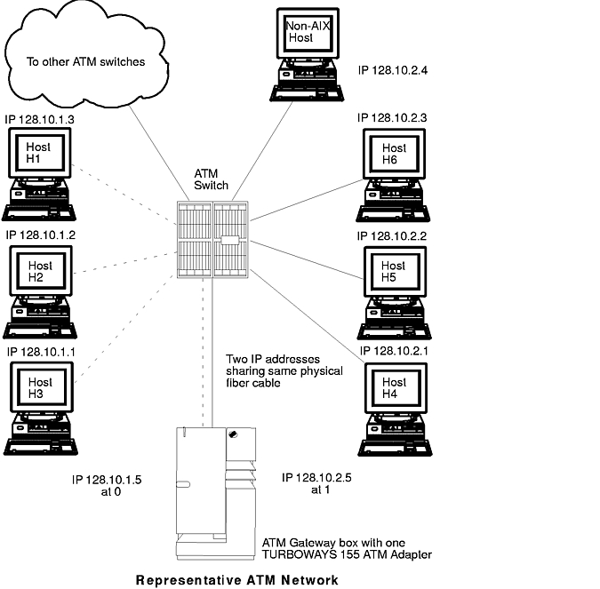
Use the Representative ATM Network figure as an example to configure your network.
Within the Representative ATM Network figure, one logical IP subnet is represented by dashed lines from each host to the switch. The other IP subnet is represented by solid lines from each host to the switch.
The following Representative Host Configuration table indicates how AIX hosts, H3 and H4, should be configured to communicate with a gateway and with each host on its own logical IP subnet.
| Representative Host Configuration |
| Network Interface Driver |
VPI:VCI |
Comment |
| Host H3 |
| at0 |
0:40 |
Connection to 128.10.1.5 (gateway) |
| at0 |
0:42 |
Connection to 128.10.1.2 |
| at0 |
0:43 |
Connection to 128.10.1.3 |
| Host H4 |
| at0 |
0:50 |
Connection to 128.10.2.5 (gateway) |
| at0 |
0:52 |
Connection to 128.10.2.2 |
| at0 |
0:53 |
Connection to 128.10.2.3 |
| at0 |
0:54 |
Connection to 128.10.2.4 |
To reach hosts on another logical IP subnet, only a VPI:VCI connection to the gateway needs to be created. (The VPI:VCIs are for illustration purposes only.)
The ATM gateway box has one ATM with two IP addresses sharing the same physical cable.
SVC Network
Using the Representative ATM Network figure as an example, imagine that AIX host H3 wishes to call H4. H1 is the ARP server for subnet 1 and H6 is the ARP server for subnet 2. Assuming a subnet mask of 255.255.255.0, stations with addresses 128.10.1.X are members of one subnet, whereas stations with addresses of 128.10.2.X are members of a second subnet. See the following list of representative host configurations using SVCs.
| List of Representative Host Configurations |
| Network Interface Driver |
IP Address |
ARP Server |
ARP Server Address |
Gateway Address |
| Host H1 |
| at0 |
128.10.1.3 |
Yes |
|
128.10.1.5 |
| Host H3 |
| at0 |
128.10.1.1 |
No |
ATM address of H1 |
128.10.1.5 |
| Gateway |
| at0 |
128.10.1.5 |
No |
ATM address of H1 |
|
| at1 |
128.10.2.5 |
No |
ATM address of H6 |
|
| Host H4 |
| at0 |
128.10.2.1 |
No |
ATM address of H6 |
128.10.2.5 |
| Host H6 |
| at0 |
128.10.2.3 |
Yes |
|
128.10.2.5 |
Note: Each subnet requires one and only one ARP server.
Because H3 recognizes that address 128.10.2.1 is not on its subnet, H3 consults H1 to resolve the default gateway's IP address to an ATM address. H3 then places a call to the gateway. The gateway recognizes that the data is bound for the second subnet and consults H6 to successfully resolve H4's IP address to an ATM address. Connections are then established between H3 and the gateway and between the gateway and H4.
Configuring an ATM Adapter
To configure your ATM 100, ATM 155, or PCI ATM adapter, use the Web-based System Manager fast path wsm network or the SMIT fast path smit chg_atm. Select an adapter name, then use the online help and multiple-choice lists to decide which changes to make for your configuration.
ATM Adapter Statistics
The atmstat command can be used for getting ATM adapter statistics. Using the atmstat command with the -r flag resets the statistics. The format of the command is atmstat DeviceName. This command returns the following sets of statistics:
Transmit Statistics
- Packets:
- This field contains the number of packets (or PDUs) transmitted.
- Bytes:
- This field contains the count of bytes transmitted. These are the user bytes. The ATM overhead, for example, ATM cell header, AAL 5 PDU trailer, etc., are excluded.
- Interrupts:
- This field is not used.
- Transmit Errors:
- This field contains the number of Transmit Errors for this device.
- Packets Dropped:
- This field contains the number of Transmit Packets that were dropped, for instance, due to out of buffers condition.
- Max Packets on S/W Transmit Queue:
- This field does not apply to ATM.
- S/W Transmit Queue Overflow:
- This field does not apply to ATM.
- Current S/W + H/W Transmit Queue Length:
- This field contains the current transmit queue length.
- Cells Transmitted:
- This field contains the number of cells transmitted by this device.
- Out of Xmit Buffers:
- This field contains the number of packets dropped because of Out of Xmit Buffers condition.
- Current HW Transmit Queue Length:
- This field contains the current number of Transmit Packets on the hardware queue.
- Current SW Transmit Queue Length:
- This field does not apply to ATM.
Receive Statistics
- Packets:
- This field contains the number of packets (or PDUs) received.
- Bytes:
- This field contains the count of Bytes received. These are the user bytes. The ATM overhead, for example, ATM cell header, AAL 5 PDU trailer, etc., are excluded.
- Interrupts:
- This field contains the number of Interrupts taken by the system for the Adapter-to-System indications. Some of the events that cause these interrupts are packet received, transmit done indication, and so on.
- Receive Errors:
- This field contains the number of Receive Errors for this device.
- Packets Dropped:
- This field contains the number of Received Packets dropped, for instance, due to out of buffers condition.
- Bad Packets:
- This field does not apply to ATM.
- Cells Received:
- This field contains the number of Cells Received by this device.
- Out of Rcv Buffers:
- This field contains the number of Packets Dropped because of out of receive buffers condition.
- CRC Errors:
- This field contains the number of Received Packets that encountered CRC errors.
- Packets Too Long:
- This field contains the number of Received Packets that exceeded the maximum PDU size.
- Incomplete Packets:
- This field contains the number of Incomplete received packets.
- Cells Dropped:
- This field contains the number of dropped cells. Cells could be dropped for a number of reasons, such as bad header error control (HEC), out of buffer condition, and so on.
General Statistics
- No mbuf Errors:
- This field contains the number of mbuf requests that were denied.
- Adapter Loss of Signals:
- This field contains the number of times the adapter encountered Loss of Signal.
- Adapter Reset Count:
- This field contains the number of times the adapter has been reset.
- Driver Flags: Up Running Simplex
- This field contains the NDD flags.
- Virtual Connections in use:
- This field contains the number of VCs that are currently allocated or in use.
- Max Virtual Connections in use:
- This field contains the maximum number of VCs allocated since the last reset of the statistics.
- Virtual Connections Overflow:
- This field contains the number of allocate VC requests that have been denied.
- SVC UNI Version:
- This field contains the current UNI version of the signaling protocol in use.
Additional ATM Statistics
Using the atmstat command with the -d flag provides detailed statistics.
Turboways ATM Adapter Specific Statistics:
- Packets Dropped - No small DMA buffer:
- This field contains the number of received packets dropped because the adapter did not have small system buffers for DMA.
- Packets Dropped - No medium DMA buffer:
- This field contains the number of received packets dropped because the adapter did not have medium system buffers for DMA.
- Packets Dropped - No large DMA buffer:
- This field contains the number of received packets dropped because the adapter did not have large system buffers for DMA.
- Receive Aborted - No Adapter Receive buffer:
- This field contains the number of received packets aborted because the adapter did not have on-card receive buffers.
- Transmit Aborted - No small DMA buffer:
- This field contains the number of transmit packets dropped because of the lack of small system buffers for DMA.
- Transmit Aborted - No medium DMA buffer:
- This field contains the number of transmit packets dropped because of the lack of medium system buffers for DMA.
- Transmit Aborted - No large DMA buffer:
- This field contains the number of transmit packets dropped because of the lack of large system buffers for DMA.
- Transmit Aborted - No MTB DMA buffer:
- This field contains the number of transmit packets dropped because of the lack of large system buffers for DMA.
- Transmit Aborted - No Adapter Transmit buffer:
- This field contains the number of transmit packets dropped because of the lack of adapter on-card transmit buffers.
- Max Hardware Transmit Queue Length:
- This field contains the maximum number of transmit packets queued in the hardware queue.
- Small Mbufs in Use:
- This field contains the number of small mbufs currently in use. The adapter device driver allocates these buffers according to the configuration information provided by system administrators. This information can be used to tune the configuration information.
- Medium Mbufs in Use:
- This field contains the number of medium mbufs currently in use. The adapter device driver allocates these buffers according to the configuration information provided by system administrators. This information can be used to tune the configuration information.
- Large Mbufs in Use:
- This field contains the number of large mbufs currently in use. The adapter device driver allocates these buffers according to the configuration information provided by system administrators. This information can be used to tune the configuration information.
- Huge Mbufs in Use:
- This field contains the number of huge mbufs currently in use. The adapter device driver allocates these buffers according to the configuration information provided by the system administrators. This information can be used to tune the configuration information.
- MTB Mbufs in Use:
- This field contains the number of MTB mbufs currently in use. The adapter device driver allocates these buffers according to the configuration information provided by the system administrators. This information can be used to tune the configuration information.
- Max Small Mbufs in Use:
- This field contains the maximum number of small mbufs that have been used. The adapter device driver allocates these buffers according to the configuration information provided by the system administrators. This information can be used to tune the configuration information.
- Max Medium Mbufs in Use:
- This field contains the maximum number of medium mbufs that have been used. The adapter device driver allocates these buffers according to the configuration information provided by system administrators. This information can be used to tune the configuration information.
- Max Large Mbufs in Use:
- This field contains the maximum number of large mbufs that have been used. The adapter device driver allocates these buffers according to the configuration information provided by system administrators. This information can be used to tune the configuration information.
- Max Huge Mbufs in Use:
- This field contains the maximum number of huge mbufs that have been used. The adapter device driver allocates these buffers according to the configuration information provided by system administrators. This information can be used to tune the configuration information.
- MTB Mbufs in Use:
- This field contains the maximum number of MTB mbufs that have been used. The adapter device driver allocates these buffers according to the configuration information provided by system administrators. This information can be used to tune the configuration information.
- Small Mbufs overflow:
- This field contains the number of times that a small mbuf could not be allocated. This information can be used to tune the configuration information.
- Medium Mbufs overflow:
- This field contains the number of times that a medium mbuf could not be allocated. This information can be used to tune the configuration information.
- Large Mbufs overflow:
- This field contains the number of times that a large mbuf could not be allocated. This information can be used to tune the configuration information.
- Huge Mbufs overflow:
- This field contains the number of times that a huge mbuf could not be allocated. This information can be used to tune the configuration information.
- MTB Mbufs overflow:
- This field contains the number of times that an MTB mbuf could not be allocated. This information can be used to tune the configuration information.
PCI ATM Adapter Specific Statistics:
- Total Receive Buffers: 48 Using: 32
- This message contains the number of receive buffers allocated as well as the number that are currently in use.
[ Previous |
Next |
Contents |
Glossary |
Home |
Search ]