


Next: Diode Circuits
Up: Filter Circuits
Previous: Amplifier with Negative Feedback
-
In the following circuit, the input signal is
 , and the components have been chosen such that
  and
and
 .
The output is at the terminals AB.
.
The output is at the terminals AB.
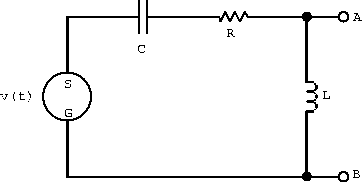
- What is the transfer function H(
 )?
)?
- Find the current in the circuit.
- What is the voltage drop across each element of the circuit?
- Show algebraically that at any instant the potential
difference around the circuit is zero.
- At time
 , where N=0,2,4,... make a sketch
showing the voltage across each element in the complex plane
and show that the vector sum of the voltage drops is equal to
the voltage supplied.
, where N=0,2,4,... make a sketch
showing the voltage across each element in the complex plane
and show that the vector sum of the voltage drops is equal to
the voltage supplied.
- Write an expression for
 .
.
- What is the limit of as
 goes to
zero?
goes to
zero?
- What is the limit of as goes to
infinity?
- What is the corner frequency?
- What is at the corner frequency?
- Make a sketch showing the characteristics of on a log-log plot. Label the slope of the curve
where possible, the corner frequency, and the value of at the corner frequency.
- Describe the high and low frequency behavior in dB/octave.
-
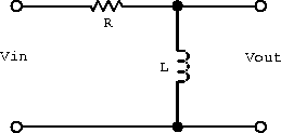
- Draw a passive LCR low-pass filter and write down the transfer
function of your four-terminal network.
- Determine approximations to the transfer function and filter
corner frequency(s).
- Write the resonance frequency,
 , in terms
of the corner frequency(s).
, in terms
of the corner frequency(s).
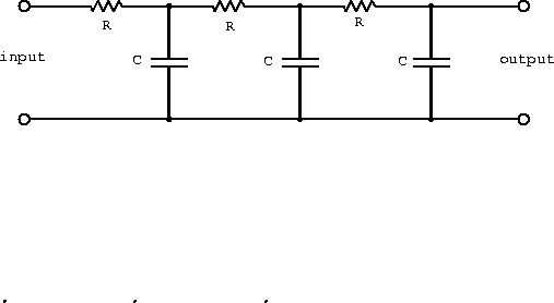
-
Write down the transfer function,
 , for the network
shown below, and from it find:
, for the network
shown below, and from it find:
- the corner frequency(s) and
- the value(s) of at the corner frequency(s).
- Sketch and the voltage phase-shift as a
function of .
- What type of filter is this?
-
- What is the transfer function for the following circuit?
- Describe the frequency response at low and high frequencies?
- Sketch the magnitude on a log-log plot.
(label slopes, the corner frequency(s), and
 )
)
- What is the signal attenuation for
 .
.
-
- Show that the transfer function of a single-pole RC filter drops
by 3 db at the corner frequency. This is often refereed to as
the 3 db down-point.
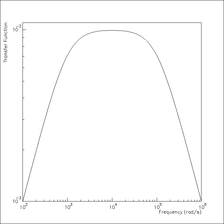
- Design a bandpass RC filter with the transfer function shown
below.
 rad/s and
  rad/s are the
3 db down-points of the RC filter sections. Choose impedances
so that the first section is not much affected by the loading of
the second section.
rad/s are the
3 db down-points of the RC filter sections. Choose impedances
so that the first section is not much affected by the loading of
the second section.
- Are
 and
and  the 3 db down-points of a bandpass
filter?
the 3 db down-points of a bandpass
filter?
Next: Diode Circuits
Up: Filter Circuits
Previous: Amplifier with Negative Feedback
Doug Gingrich
Tue Jul 13 16:55:15 EDT 1999