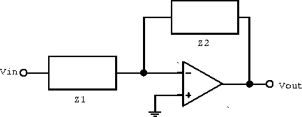
- Write an expression for the transfer function
 .
Express your result in terms of the amplitude of the output and
the phase relative to the input. Let
  k
k  ,
,

 ,
, 
 F and
F and 
 F. Do
not simplify the algebra.
- What are the (real) zeroes in the transfer function, if any?
- What are the (real) poles in the transfer function if any?
- Sketch the transfer function as a function of
 on a
log-log plot. Your sketch should show the slope of
  in the large and small
  limits, the corner
frequencies, and the value of
  at the corner
frequencies.
- Describe the dependence of the output on frequency at small and large frequencies in dB/octave.
- Write the two rules for the analysis of circuits which utilize ``ideal'' op-amps.
- Write an expression for the potential
 for the
following circuit.

- Let
 k
k  and
and  k
k  . Sketch a log-log
plot showing the function
  for the above
circuit assuming that a general purpose op-amp such as the 741
is used.
- The 741 op-amp has a corner frequencies of 4 Hz, DC open-loop
gain of
 and a fall off at high frequency of
6 dB/octave. What is the frequency domain over which the
amplifier defined in part (c) will have constant gain? What is
the gain of the amplifier in this frequency domain?
- Suppose now that the impedance
 is replaced with a
capacitor with a capacitance C (
  k
k  ). For
frequencies much greater than 4 Hz, the 741 op-amp will
attenuate the signal if the product RC is greater than some
maximum value. For a frequency of 50 kHz, what is the maximum
value for C for which the op-amp
  will not
attenuate the output signal at high frequencies? Hint: If
you sketch
  and
and  , you will be
able to see the constraint on
  .
.
![]()
Hint: the input is ![]() .
.