PDFs & Technicians Graduates Undergraduates Past Students
Craig Slepicka

4rd Year BSc, Mechanical Engineering
Supervisors
Dr. Bob Koch, Dr. David S. Nobes
My time working for Dr. Nobes and Dr. Koch during the summer of 2012 was an amazing experience. It showed the research aspect of engineering that I have always found intriguing. It forced me to use the knowledge I have gained from my undergraduate degree and tested my problem solving skills by adapting that knowledge to fix unique problems. I would recommend this opportunity to anyone considering continuing their schooling.
Design of a control system to use an oscillating airfoil to interact with on coming vortices and either enhance or suppress them
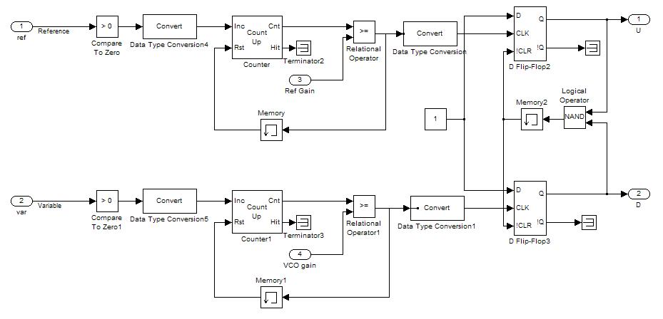
Charge pump
New Design for Vortex Detection
Project Description
The goal of this project was to design a control system to use an oscillating airfoil to interact with on coming vortices and either enhance or suppress them. This was a continuation of Mathew Bussiere's Masters research project.
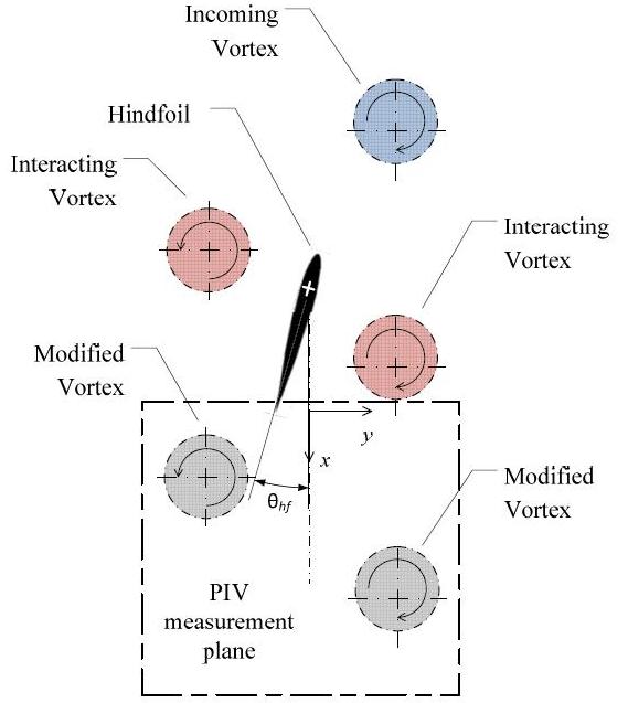
Setup
The setup for the apparatus consists of two airfoils in tandem, in the water channel. As water flows past the upstream airfoil, its oscillations produce vortices. A detector is placed between the two airfoils to determine the frequency and phase of the incoming vortices. The rear airfoil will then be controlled to interact with these vortices. It is assumed any information about the upstream airfoil is unknown and the only information about the incoming vortices is given by the vortex detector.
Control System
The stepper motor controller was designed in Simulink and uses dSpace work board to send and receive signals. The first step was to modify the code to be able to dynamically change the oscillation parameters like the frequency, amplitude and phase. The next step was designing a system that could lock onto the vortex pressure signal and produce a signal that could control the stepper motor. This was done with a Phase Lock Loop built in Simulink.
Dynamic Modifications
The original system was limited by the stepper motors inability to follow a step change. For the amplitude and phase, this situation was solved by inputting a first-order transfer function that behaved as a low pass filter. By doing so this smoothed out the step change so that the stepper motor would be able to follow the signal.
To solve the issue with the frequency a modulo integrator was implemented. This integrated the frequency to give the phase for the sine function to follow and by doing so smoothed out any steps that might occur in the frequency.
Phase-lock Loop
The objective of the Phase-lock Loop (PLL) was to lock onto a signal which was corresponding to the incoming vortices and then output a smooth sine wave for the motor to follow. To change how the airfoil interacts with the vortices, it would be ideal for the output signal to have an adjustable phase compared to the vortex signal. This was accomplished through a time-delay block that delays the signal an amount of time to correspond to the particular phase specified.
To make the controller as robust as possible it was also designed to output a signal that has a multiple frequency of the locked on signal. To achieve this a counting system was placed into the charge pump to make either the reference signal or the generated appear to PLL that it was operating at a frequency multiple of itself.
Vortex Detection
The goal of this part of the project was to design a system that produced a signal characteristic to the incoming vortices. The signal also had to be "clean" enough so that the Phase-lock Loop could lock onto it.
Original System
The original system was a pressure membrane on the downstream airfoil that sent a pressure signal to a pressure transducer. This was able to show that the vortices did contribute to the pressure signal as each phase offset had a unique signal as was shown by Mathew Bussiere. The issue was that the system was not sensitive enough to pick up the vortices' pressure fluctuations and difficult to find the contributions from the vortices in the signal so a new system had to be designed.
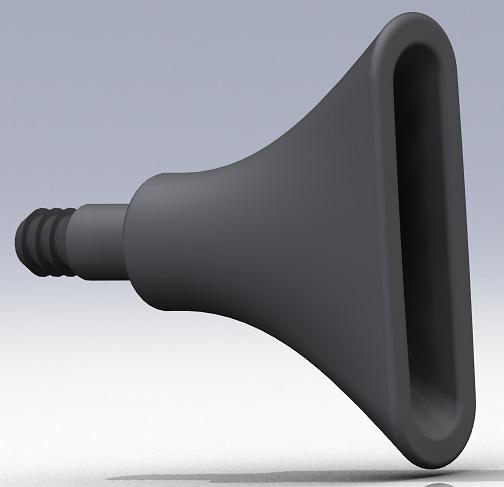
New Design
The new design is an adaptation of a pitot tube. A pitot tube was found to have to slow of a response time when filled with water. To compensate for this a horn will be made to have a membrane on the front so air can be used, instead of water, to transmit the dynamic pressure to the pressure transducer.