PDFs & Technicians Graduates Undergraduates Past Students
Eric Penner
3rd Year BSc, Mechanical Engineering
Supervisors
Dr. David S. Nobes
Description of Coop Workterm (Jan - August 2010)
This work term was an excellent learning experience and has made me better prepared for practicing engineering. My job description was basically to help the grad students with their projects. This covered helping with the solidmodels, drawings, talking with the shop, programming for devices, and setting up and testing the apparatus's. The variety of projects and tasks always kept me busy and learning. I enjoyed being involved in the design process through to production and use of the apparatus, and found it a nice and useful change from the class room. The biggest learning curve was with programming the devices used in the experiments, it was also the most rewarding once I got the hang of it. I would recommend this job for people interested in a hands on engineering experience or if you are interested in grad school.
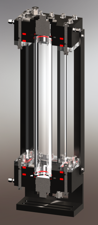
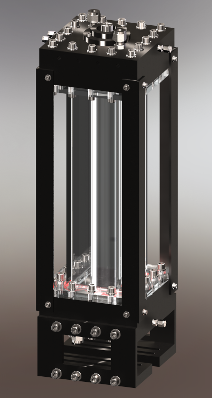
Settling Chamber
Left: Section View (red shows o-rings)
Right: Complete View
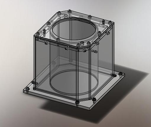
The mixing chamber rig

The streamline plot from DaVis
Settling Chamber
The settling chamber project was designed to study the effect of high frequency pressure waves on particles in a fluid. The end goal of the project is to use high frequency pressure waves to seperate particles out of slurries. The heart of the device is two ultrasonic piezo transducers at either end of a 1 foot long 1 inch ID acyrlic tube. Both transducers can generate and detect pressure waves. The resonant frequency of the piezo transducers is 500 kHz, so the experiments are done around this frequency.
Stereo PIV (particle image velocimetry) was used to analyze the motion of the particles.
I helped finalize the design and produced the drawings.
I also wrote the code to control the function generator and oscilliscope. The oscilliscope is used for listening to the transducers. The oscilliscope code allows control of most scope features as well as logging the waveform to the computer. We couldn't use a DAQ because the temporal resolution was not accurate enough. The oscilliscope can sample at 200 MHz. The disadvantage is that you cannot continously log from the scope.
The function generator was used to drive the transducers. The motivation for coding the function generator was automating frequency and amplitude sweeps, logging each resulting waveform with the scope and analyzing data with algorithms. This reduces human error, monotony, and saves time.
This video from Hielscher demonstrates water droplets getting forced to the nodes.
Mixing Chamber
The mixing chamber project was designed to study the motion of particles in industrial mixers. The motivation was to develop better models to predict wear on tanks.
I was involved in the design of the tank. I made the solid models. I also helped run the preliminary experiments.
There were a number of design constraints:
- The curvature of the tank distorts the image. This was overcome by matching the refractive index of the fused silica tube with Drakol #5 and controlling the temperature of the oil with a heat bath.
- Both Camera's had to be in forward scatter to match image intensity
- The laser sheet would effectivly terminate at the impeller, so the viewing area was reduced.
Programming
One of my primary jobs was to write programs to communicate with devices in the lab. Many of the incoming grad students are not familiar with writing programs to control devices. If all of the lab devices have individual programs, then the grad students learning curve is reduced to incorporating the devices they want into one control program.
The SDK I used was National Instruments LabWindows/CVI. It is an ANSI C based language that handles the GUI very nicely. I used the RS232 and GPIB communications example programs from CVI as backbones of most of my programs.