This tutorial explains how to connect and configure an Xbee S6 wifi module using the DE0 Nano board and send an HTTP request to a test page. We sent our test request to a laptop running WAMP on a local network that we set up with a router, but this tutorial should work for any network you can connect to using WPA2 Personal.
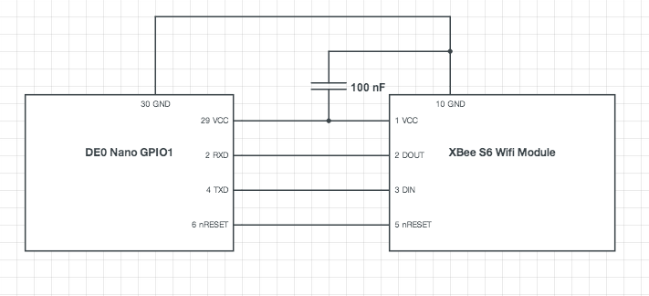
The minimum configuration for connecting the Xbee wifi module to the DE0 board uses the VCC, DOUT, DIN, and GND pins on the Xbee. We've use this basic configuration along with the active-low reset pin nRESET, which makes some testing easier when configuring the module in software.
The Xbee S6 wifi module uses a different spacing than the perfboards that we use in the lab. There are numerous breakout boards available from vendors such as SparkFun, or you can a header and spread the pin connections apart.
The easiest way to get started with this appnote is to download the Quartus archive file de0_nano_system.qar. Once you've downloaded it:
- Double-click the archive file to open it up in Quartus.
- Quartus will bring up a dialog box to Restore Archived Project. The default destination folder will be {location of archive file}/de0_nano_system_restored. Rename it to /WifiDemo and click OK.
- Compile the design. You'll have warnings but there should be no errors.
- Program your DE0 Nano.
- Go to WifiDemo/Appnote/README.txt for instructions on how to set up the software.
That's all you need to get going! The Microcontroller section gives more details about how the project was built that might be useful if you want to integrate wifi into a preexisting project. The Software section has similar instructions to README.txt but also includes some commentary about the functions used to interface with the Xbee wifi module.
We built this project using Quartus II 32-bit Version 12.1 Build 243 01/31/2013 SJ Full Version with Service Pack 1.22. The CPU was interconnected using Qsys 12.1sp1 Build 243.
This section assumes you have a preexisting Quartus project and illustrates how to add the Qsys and toplevel entities needed to program your FPGA to be a wifi-enabled device.
For the full summary of the Qsys system, see system.html.
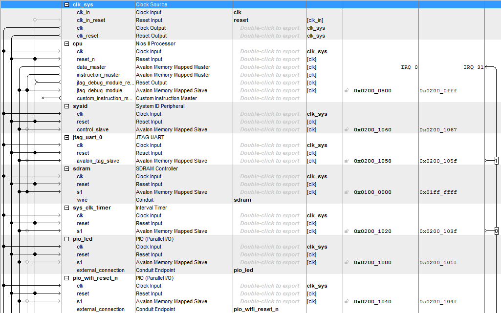
- From Quartus, open up Qsys by going to Tools > Qsys. You will need to have at least the following components:
-
Clock source
clk_sys
- export clk_in as clk
- export clk_in_reset as reset
- Nios II Processor cpu
- System ID Peripheral sysid
- JTAG UART jtag_uart_0
-
SDRAM Controller
sdram
- export wire as sdram
- Interval Timer sys_clk_timer
-
PIO (Parallel I/O)
pio_led
- Width 8
- Direction output
- export external_connection as pio_led
-
PIO (Parallel I/O)
pio_wifi_reset_n
- Width 1
- Direction output
- export external_connection as pio_wifi_reset_n
-
RS232 UART
uart_wifi
- Baud rate 9600
- Parity None
- Data bits 8
- Stop bits 1
- export external_interface as uart_wifi
-
Clock source
clk_sys
- Connect all clocks.
- Connect all resets using System > Create Global Reset Network.
- Assign base addresses using System > Assign Base Addresses.
Your final Qsys setup should look similar to this:

For the full toplevel file, see de0_nano_system.vhd.
- Add your Qsys file using Project > Add/Remove Files in Project.
- Import the pin assignments in DE0.qsf using Assignments > Import Assignments.
The toplevel entity is shown below: there are signals for the clock, DRAM, and LED, but the one we're interested in is GPIO_1, which we'll use to connect our wifi module. You can also use GPIO_0.
entity de0_nano_system is
  port ( -- Input clock
         CLOCK_50     : in  std_logic;

         -- DRAM interface
         DRAM_CLK     : out   	std_logic;                       	-- Master Clock
         DRAM_CKE     : out   	std_logic;                       	-- Clock Enable
         DRAM_CS_N    : out   	std_logic;                       	-- Chip Select
         DRAM_RAS_N   : out   	std_logic;                       	-- Row Address Strobe
         DRAM_CAS_N   : out   	std_logic;                       	-- Column Address Strobe
         DRAM_WE_N    : out   	std_logic;                       	-- Write Enable
         DRAM_DQ      : inout 	std_logic_vector(15 downto 0);   	-- Data I/O (16 bits)
		 DRAM_DQM	  : out		std_logic_vector(1 downto 0);	   	-- Output Disable/Write Mask
         DRAM_ADDR    : out   	std_logic_vector(12 downto 0);   	-- Address Input (13 bits)
		 DRAM_BA	  : out		std_logic_vector(1 downto 0);	   	-- Bank Address

         -- Parallel I/O
		 LED		 : out   	std_logic_vector(7 downto 0);	   	-- LEDs
		 GPIO_1		 : inout 	std_logic_vector(33 downto 0)	   	-- 2 x 40 Expansion Header
       );
end entity de0_nano_system;
Here's how the component that we created in Qsys is declared:
component system is
  port ( -- Clock and reset
		 clk_clk              		: in    std_logic                     	:= 'X';             	-- clk
		 reset_reset_n        		: in    std_logic                     	:= 'X';             	-- reset_n

		 -- DRAM
		 sdram_addr           		: out   std_logic_vector(12 downto 0);                    		-- addr
		 sdram_ba             		: out   std_logic_vector(1 downto 0);                     		-- ba
		 sdram_cas_n          		: out   std_logic;                                        		-- cas_n
		 sdram_cke            		: out   std_logic;                                        		-- cke
		 sdram_cs_n           		: out   std_logic;                                        		-- cs_n
		 sdram_dq             		: inout std_logic_vector(15 downto 0) 	:= (others => 'X'); 	-- dq
		 sdram_dqm            		: out   std_logic_vector(1 downto 0);                     		-- dqm
		 sdram_ras_n          		: out   std_logic;                                        		-- ras_n
		 sdram_we_n           		: out   std_logic;                                         		-- we_n

		 -- Parallel I/O
		 pio_led_export				: out	  std_logic_vector(7 downto 0);							-- export

		 -- Wifi module
		 uart_wifi_rxd				: in	  std_logic						:= 'X';					-- receive
		 uart_wifi_txd				: out	  std_logic;											-- transmit
		 pio_wifi_reset_n_export	: out	  std_logic												-- export
	   );
end component system;
This component is instantiated and mapped to our toplevel:
inst_cpu : system
  port map ( -- Clock and reset
			 clk_clk              		=> clk_sys,
			 reset_reset_n        		=> pll_locked,

				  -- DRAM
			 sdram_addr           		=> DRAM_ADDR,
			 sdram_ba             		=> DRAM_BA,
			 sdram_cas_n          		=> DRAM_CAS_N,
			 sdram_cke            		=> DRAM_CKE,
			 sdram_cs_n           		=> DRAM_CS_N,
			 sdram_dq             		=> DRAM_DQ,
			 sdram_dqm            		=> DRAM_DQM,
			 sdram_ras_n          		=> DRAM_RAS_N,
			 sdram_we_n           		=> DRAM_WE_N,

			 -- Wifi module
			 uart_wifi_rxd				=> GPIO_1(0), 	-- pin 2
			 uart_wifi_txd				=> GPIO_1(1),	-- pin 4
			 pio_wifi_reset_n_export	=> GPIO_1(3)	-- pin 6
		   );
The microcontroller communicates with the wifi module ovver serial UART. The microcontroller sends data to the Xbee out on uart_wifi_txd, which is mapped to GPIO 1 pin 2, and receives data from the Xbee on uart_wifi_rxd, which is mapped to pin 4. Pin 6 carries the active-low reset signal.
For the full main software file, see main.c.
- Open Nios II Software Build Tools for Eclipse. We used version 12.1sp1 (12.1.1.243).
- Create a new project using File > New > Nios II Application and BSP from Template.
- Browse for the SOPC Infromation File and select system.sopcinfo in your project folder.
- Name your project—we called ours WifiDemo—and use the template Hello MicroC/OS-II. Click Finish.
- Replace the default file hello_ucosii.c with main.c.
- Right-click on your project and click Refresh (F5), then go to Project > Clean..., choose Clean all projects, and click OK.
- Open up main.c. If you have any unresolved inclusions, build the project using Project > Build (Ctrl + B). There should be no more errors.
- Enter your network details in the defines at the top of main.c.
- Right-click on your project and click Run > Run as > NIOS II Hardware. You may need to run the project again; I've noticed that the program may not print to the console on the first run after programming the device.
- If there is an error when you run your project, you may need to go to Run > Run Configurations > Target Connection > Refresh Connections.
The RS232 component that we added in Qsys is memory mapped to UART_WIFI_BASE. Any data written to that memory location in software will be forwarded out uart_wifi_txd (pin 4), and any data received on uart_wifi_rxd (pin 2) is forwarded to that memory location.
The University Program RS232 UART component provides a nice API for reading from and writing to UART_WIFI_BASE. This is similar to the API for writing to the LCD on the DE2. We first enable the wifi module by holding PIO_WIFI_RESET_N high, and then open a UART device.
// Enable the wifi module.
IOWR_ALTERA_AVALON_PIO_DATA(PIO_WIFI_RESET_N_BASE, 1);
// Open wifi UART device.
wifi_dev = alt_up_rs232_open_dev(UART_WIFI_NAME);
To write to the wifi module, we disable read interrupts and check if there is space in the write FIFO. If there is no space, we wait and retry.
/**
 * Writes a message to the wifi UART device.
 * The message will be used to configure the Xbee wifi module, if the device is in configuration mode,
 * or it will be forwarded through TCP to the remote server given by DL (the destination IP address)
 * and DE (the destination IP port).
 * @param message - the message to write
 */
void wifiWrite(char *message) {
	int i = 0;
	alt_up_rs232_disable_read_interrupt(wifi_dev);
	char data = message[i];
	while (data != '\0') {
		// Check for write space.
		unsigned writeAvailable = alt_up_rs232_get_available_space_in_write_FIFO(wifi_dev);
		WRITE_LOG(printf("[WifiWrite] available: %u\n", writeAvailable));
		if (writeAvailable > WRITE_FIFO_EMPTY) {
			// If space, write the character.
			WRITE_LOG(printf("[WifiWrite] data: %c\n", data));
			int status = alt_up_rs232_write_data(wifi_dev, data);
			// Log errors.
			if (status != OK) WRITE_LOG(printf("[WifiWrite] error: cannot write\n"));
			// Go to next character.
			data = message[++i];
			OSTimeDlyHMSM(0, 0, 0, 2);
		} else {
			// If no space, wait.
			WRITE_LOG(printf("[WifiWrite] waiting for space\n"));
			OSTimeDlyHMSM(0, 0, 0, 100);
		}
	}
	alt_up_rs232_enable_read_interrupt(wifi_dev);
}
Similarly, to read, we check if there are characters available in the read buffer. We keep reading until we reach a stop character, such as a carriage return '\r' or newline '\n'. In this demo we've used a fix-sized read buffer of size WIFI_READ_MAX_SIZE, so we also stop reading when we reach this size as checked by the function inRange(). We also check how many times there is no data in the read buffer, and stop reading after receiving WIFI_READ_AVAILABLE_RETRIES empty results, as checked by the function inRetryRange().
/**
 * Listens on the wifi UART until a full message is received.
 * @param stop - the string marking the end of the message
 * @return the message that was received, which must be freed by the caller
 */
WifiMessage *wifiReadUntil(char *stop) {
	alt_u8 data, parity;
	unsigned readAvailable;
	int stopLength = strnlen(stop, WIFI_READ_STOP_MARKER_MAX_SIZE);
	READ_LOG(printf("[WifiRead] stop: %s\n", stop));
	// Create a new, empty message.
	WifiMessage *message = malloc(sizeof(*message));
	wifiMessageClear(message);
	// Count the number of retries when there is no data available.
	int retryCount = 0;
	// Read until the message buffer matches the stop string, or we run out of space, or there are to many retries.
	while (inRange(message->length) && inRetryRange(retryCount) &&
			!stringEndsWith(message->content, message->length, stop, stopLength)) {
		// Check for next character.
		readAvailable = alt_up_rs232_get_used_space_in_read_FIFO(wifi_dev);
		READ_LOG(printf("[WifiRead] available: %u\n", readAvailable));
		// Is there data?
		if (readAvailable <= READ_FIFO_EMPTY) {
			// No data; retry.
			retryCount++;
		} else {
			// Reset the retry count.
			retryCount = 0;
			// Get the new data.
			while (readAvailable > READ_FIFO_EMPTY) {
				// Read next character.
				int status = alt_up_rs232_read_data(wifi_dev, &data, &parity);
				// Log errors.
				if (status != OK) READ_LOG(printf("[WifiRead] error: cannot read\n"));
				// Add character to the message buffer.
				READ_LOG(printf("[WifiRead] data: %c\n", data));
				message->content[message->length] = (char)data;
				message->length++;
				// Check for next character.
				readAvailable = alt_up_rs232_get_used_space_in_read_FIFO(wifi_dev);
			} READ_LOG(printf("[WifiRead] length: %d\n", message->length));
		}
	}
	// Return the message.
	return message;
}
We are operating our wifi module in transparent mode. In transparent mode, we enter configuration by sending three '+' characters within one second, with a one-second guard time before and after the trio of plusses, and then send AT commands to read or set properties. The AT commands have the form ATCC[value], where CC is a two-charcter code identifying the command and [value] is the optional value to set. If no value is provided, the Xbee wifi module will return the current value of the property. We have used two methods to confirm wifi operation at startup: a status method which returns the current settings, and a setup method which sets the properties to the values needed to connect to the network. The Xbee will save the settings in non-volatile memory, so the setup method only needs to be called when settings are changes.
/**
 * Prints the current status of the wifi module.
 */
void wifiStatus() {
	printf("[WifiStatus]\n");
	wifiConfigEnter();      // Enter command mode.
	wifiConfigGet("VR");  	// Print firmware version.
	wifiConfigGet("ID");  	// Print the target SSID.
	wifiConfigGet("EE");  	// Print the security type (0 = None, 1 = WPA, 2 = WPA2, 3 = WEP).
	wifiConfigGet("AH");  	// Print the network type (0 = Joiner, 1 = Creator, 2 = Infrastructure).
	wifiConfigGet("IP");  	// Print the IP protocol (0 = UDP, 1 = TCP).
	wifiConfigGet("MA");  	// Print the IP addressing mode (0 = DHCP, 1 = Static).
	wifiConfigGet("DL");  	// Print the destination IP address.
	wifiConfigGet("DE");  	// Print the destination port number.
	waitForWifiReady();
	wifiConfigGet("MY");  	// Print the IP address.
	wifiConfigGet("CN");  	// Exit command mode.
}

/**
 * Sets up the wifi module to connect to the network.
 */
void wifiSetup() {
	wifiConfigEnter();
	wifiConfigGet("VR");             		// Print firmware version.
	wifiConfigSet("ID", SSID);        		// Set the target SSID.
	wifiConfigSet("EE", "2");            	// Set the security type to WPA2.
	wifiConfigSet("PK", SECURITY_KEY);  	// Set the security key.
	wifiConfigSet("AH", "2");            	// Set the network type to Infrastructure.
	wifiConfigSet("IP", "1");            	// Set the IP protocol to TCP.
	wifiConfigSet("MA", "0");            	// Set the IP addressing mode to DHCP.
	wifiConfigSet("DL", SERVER_ADDRESS);	// Set the destination IP address.
	wifiConfigSend("DE", SERVER_PORT);      // Set the destination port.
	waitForWifiReady();
	wifiConfigGet("MY");             		// Print the IP address.
	wifiConfigGet("WR");             		// Write the settings to non-volatile memory.
	wifiConfigGet("CN");             		// Exit command mode.
}
To test the connection, we make a simple GET request and read the response.
/**
 * Sends an HTML GET request.
 * @param url the url to retrieve
 */
void wifiHttpGet(char *url) {
	char request[WIFI_HTTP_REQUEST_MAX_LENGTH];
	snprintf(request, WIFI_HTTP_REQUEST_MAX_LENGTH,
			"GET %s HTTP/1.1\r\n"
			"Host: %s\r\n"
			"Content-Length: 0\r\n"
			"\r\n", url, SERVER_HOSTNAME);
	wifiWrite(request);
	printf("\n%s", request);
}

/**
 * Waits for an HTML response from the server.
 */
void wifiHttpRead() {
	WifiMessage *response = wifiReadUntil("