Tunnel configurations allow you to specify a large number of parameters to ensure interoperability with other IP Security implementations. Some examples are given here to explain the functions that can be selected.
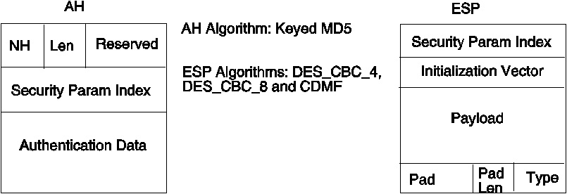
The packets are formed using AH headers for authentication, ESP headers for encryption, or the new ESP header that allows both encrypted data and an authentication digest in the same packet (see figure).
To configure a tunnel using DES CBC MD5, the combined ESP header is used with the ESP encryption algorithm set to DES_CBC_8 and the AH authentication algorithm set to HMAC MD5. To use this authentication algorithm, specify it with the -b flag, and its keys with the -c flag. For example:
gentun -v 4 -t manual -s 5.5.5.19 -d 5.5.5.23
-e DES_CBC_8 -b HMAC_MD5 -N 2349473
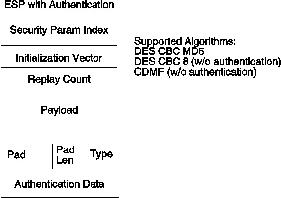
This command will generate a tunnel using DES CBC MD5 with autogenerated keys (see figure). The encrypted data and the authentication data are both contained in the same ESP header. It also supports replay preventions, which is not recommended for manual tunnels. It is included in this release for compatibility with other implementations and for testing purposes.
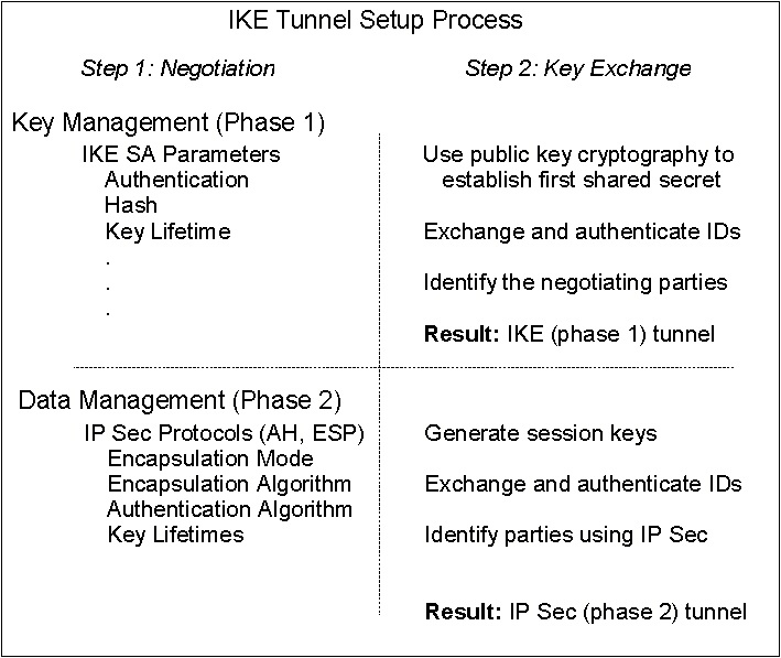
Internet Key Exchange (IKE) tunnels have more complex policy parameters; therefore, the Web-based System Manager interface is needed to configure IKE tunnels. Creating IKE tunnels differs from creating IBM or manual tunnels because the setting of security policy is a separate process from defining tunnel endpoints. In IKE, there is a two-step negotiation process, called phases, and each phase can have separate security policies.
When the Internet Key negotiation starts, it must set up a secure channel for the negotiations. This is known as the key management phase or phase 1. During this phase, each party uses preshared keys to authenticate the other and pass ID information. This phase sets up a security association during which the two parties determine how they plan to communicate securely and then which protections are to be used to communicate during the second phase. The result of this phase is an IKE or phase 1 tunnel.
The second phase is known as the data management phase or phase 2 and uses the IKE tunnel to create the IP Sec security associations for AH and ESP that actually protect traffic. The second phase also determines the data that will be using the IP Sec tunnel. For example, it can specify a subnet mask or a protocol and port number combination. (See figure.)
In many cases, the endpoints of the key management (IKE) tunnel will be the same as the endpoints of the data management (IP Sec) tunnel. The IKE tunnel endpoints are the IDs of the machines carrying out the negotiation. The IP Sec tunnel endpoints describe the type of traffic that will use the IP Security tunnel. For simple host-to-host tunnels, in which all traffic between two tunnels is protected with the same tunnel, the phase 1 and phase 2 tunnel endpoints are the same. When negotiating parties are two gateways, the IKE tunnel endpoints are the two gateways and the IP Sec tunnel endpoints are the machines or subnets (behind the gateways) of the tunnel users.
To set up an IKE tunnel, the endpoints of the negotiation must be specified. These are the two machines that plan to send and validate IKE messages. You assig a name to this tunnel, which may describe the tunnel endpoints such as VPN Boston or VPN Acme. Hosts are identified by:
When configuring an IKE tunnel through the Web-based System Manager PC Services application, you can choose from several predefined key management policies that will work for most situations. They vary according to the type of encryption and authentication algorithms specified.
Also, you can customize key management policy by specifying the parameters to be used during IKE negotiation. For Phase 1, the user must determine certain key management security properties with which to carry out the exchange. These properties are fully described in the help available with Web-based System Manager or SMIT and in the documentation for the ike command.
The data management policy parameters are the same IP Sec parameters used in IBM and manual tunnels. They describe the type of protection to be used for protecting data traffic in the tunnel. You can start more than one phase 2 tunnel under the same phase 1 tunnel. For instance, if different subnets exist between two gateways, they can have separate phase 2 tunnels, using different data management policies under the same phase 1 protection.
The data management parameters are fully described in the help available with Web-based System Manager or SMIT and in the documentation for the ike command.
There are typical scenarios that describe the type of situations most customers encounter when trying to set up tunnels. They can be described as the branch office, business partner, and remote access cases.
In the branch office case, the customer has two trusted networks that they want to connect together, for instance connecting the engineering group of one location to the engineering group of another. In this example, there are gateways that connect and all the traffic passing between the gateways use the same tunnel. The traffic at either end of the tunnel is decapsulated and passes in the clear within the company intranet.
In the first phase of the IKE negotiation, the IKE security association is created between the two gateways. The traffic that passes in the IP Security tunnel is the traffic between the two subnets, and the subnet IDs are used in the phase 2 negotiation. After the security policy and tunnel parameters are entered for the tunnel, a tunnel number is created. To start the tunnel, use the ike command.
In the business partner scenario, the networks are not trusted, and the network administrator may want to restrict access to a smaller number of hosts behind the security gateway. In this case, the tunnel between the hosts will carry traffic protected by IP Sec for use between two particular hosts. This would set the protocol of the phase 2 tunnel to be AH or ESP.
In the remote access case, the tunnels would be setup on demand, and a high level of security would be applied. The IP addresses may not be meaningful, therefore, fully qualified domain names or user at fully qualified domain names would be preferred. Optionally, you can use KEYID to relate a key to a host ID.
To start a tunnel negotiation or to allow the incoming system to act as a responder (depending on the role that is specified), the ike command can be used with a tunnel number, as shown in the following example:
ike cmd=activate numlist=1
The IP addresses can also be used. For example:
ike cmd=activate ipaddr=9.3.97.100,9.3.97.256
Since it may take several seconds for the commands to complete, the command will return once the negotiation is started. To ensure the command was successful, use the list option to display the tunnel status.
ike cmd=list

Phase 1 Tunnel ID       [1]
Phase 2 Tunnel ID       [1]
This will show the phase 1 and phase 2 tunnels that are currently active. To do a verbose listing of the tunnel,
ike cmd=list verbose


Phase 1 Tunnel ID       1
Local ID Type:          IPv4_Address
Local ID:               9.3.97.3
Remote ID Type:         IPv4_Address
Remote ID:              9.3.97.245
Mode:                   Aggressive
Security Policy:        pair1
Role:                   Initiator
Proposal:
Transform:
Encryption Alg:         ESP_DES_IV64
Auth Alg:               Preshared Key
Hash Alg:               AH_MD5
Key Lifetime:		1 Seconds *
Key Lifesize:		3264 Kbytes *
Key Rem Lifetime:	49520 Seconds
Key Rem Lifesize:	0 Kbytes
Key Refresh Overlap:	0%
Tunnel Lifetime:	1 Seconds *
Tunnel Lifesize:	20864 Kbytes *
Tun Rem Lifetime:	1584 Seconds
Tun Rem Lifesize:	0 Kbytes
Encap Mode:		N/A
Status:			2 (which translates as?)

Phase 2 Tunnel ID       1
Local ID Type:		IPv4_Address
Local ID:		9.3.97.3
Local Subnet Mask:	N/A
Local Port:		any
Local ID Type:		IPv4_Address
Remote ID:		9.3.97.245
Remote Subnet Mask:	N/A
Remote Port:		23
Mode:			Oakley_quick
Security Policy:	pair1
Role:			Initiator
Proposal:
Transform:
Encryption Alg:		ESP_3DES
Auth Alg:		HMAC-SHA
PFS:			No
SA Lifetime:		1 Seconds *
SA Lifesize:		28800 Kbytes *
SA Rem Lifetime:	0 Seconds
SA Rem Lifesize:	0 Kbytes
Key Refresh Overlap:	90
Tunnel Lifetime:	1 Seconds *
Tunnel Lifesize:	20864 Kbytes *
Tun Rem Lifetime:	1584 Seconds
Tun Rem Lifesize:	0 Kbytes
Tun Refresh Overlap:	0
Assoc P1 Tunnel:	0
Encap Mode:		N/A
Status:			2 (which translates to?)
Activating the IKE tunnel will cause filter rules for the new tunnel to be inserted into the dynamic filter table. These entries can be viewed using the lsfilt command with the -d option for dynamic filter rules:
1 permit 0.0.0.0 0.0.0.0 0.0.0.0 0.0.0.0 no udp eq 4001 eq 4001 both both no all packets 0 al
l
2 *** Dynamic filter placement rule *** no
0 permit 0.0.0.0 0.0.0.0 0.0.0.0 0.0.0.0 yes all any 0 any 0 both both no all packets 0 all

*** Dynamic table ***

0 permit 0.0.0.0 0.0.0.0 0.0.0.0 0.0.0.0 no udp eq 500 eq 500 local both no all packets 0
0 permit 0.0.0.0 0.0.0.0 0.0.0.0 0.0.0.0 no ah any 0 any 0 both inbound no all packets 0
0 permit 0.0.0.0 0.0.0.0 0.0.0.0 0.0.0.0 no esp any 0 any 0 both inbound no all packets 0
1 permit 10.10.10.1 255.255.255.255 10.10.10.4 255.255.255.255 no all any 0 any 0 both outbound yes all packets 1
1 permit 10.10.10.4 255.255.255.255 10.10.10.1 255.255.255.255 no all any 0 any 0 both inbound yes all packets 1
This example shows a machine that has one IKE tunnel and no other tunnels. The dynamic filter rule (rule #2 in this example of the static table) can be moved by the user to control placement relative to all other user-defined rules. The rules in the dynamic table are constructed automatically as tunnels are negotated and corresponding rules are inserted into the filter table. These rules can be displayed, but not edited.
To turn on logging of the dynamic filter rules, the logging option for rule #2 is set to yes:
chfilt -v 4 -n 2 -l y
For more details on logging of IKE traffic, see the section on Logging Facilities.
To deactivate the tunnel, use the remove option.
ike cmd=remove numlist=1
There are several predefined filter rules that are autogenerated with certain events. When the ipsec_v4 or ipsec_v6 device is loaded, a predefined rule is inserted into the filter table and then activated. By default, this predefined rule is to permit all packets, but it is user configurable and you can set it to deny all packets.
Note: When configuring remotely, ensure that the deny rule is not enabled before the configuration is complete. This will keep your session from getting shut out of the machine. The situation can be avoided either by setting the default action to permit or by configuring a tunnel to the remote machine before activating ipsec.
There is a predefined rule for both IPv4 and IPv6 filter tables. Either may be independently changed to deny all. This will keep traffic from passing unless that traffic is specifically defined by additional filter rules. The only other option to change on the predefined rules is chfilt with the -l option, which allows packets matching that rule to be logged.
To support IKE tunnels, a dynamic filter rule is placed in the IPv4 filter table. This is the position at which dynamic filter rules are inserted into the filter table. This position can be controlled by the user by moving its position up and down the filter table. Once the tunnel manager daemon and isakmpd daemon are initialized that will allow IKE tunnels to be negotiated, rules are automatically created in the dynamic filter table to handle IKE messages as well as AH and ESP packets.
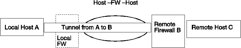
The host-firewall-host configuration option for tunnels (see figure) allows you to create a tunnel between your host and a firewall, then automatically generate the necessary filter rules for correct communication between your host and a host behind the firewall. The auto-generated filter rules permit all rules between the two non-firewall hosts over the tunnel specified. The default rules--for user datagram protocol (UDP), Authentication Headers (AH), and Encapsulating Security Payload (ESP) headers--should already handle the host to firewall communication. The firewall will have to be configured appropriately to complete the setup. You should use the export file from the tunnel you created to enter the SPI values and keys that the firewall needs.
This section describes the configuration and format of system logs relating to IP Sec. As hosts communicate with each other, the transferred packets may be logged to the system log daemon, syslogd. Other important messages about IP Sec will appear as well. An administrator may choose to monitor this logging information for traffic analysis and debugging assistance. The following are the steps for setting up the logging facilities.
local4.debug var/adm/ipsec.log
Use the local4 facility to record traffic and IP Sec events. Standard AIX priority levels apply. You should set the priority level of debug until traffic through IP Security tunnels and filters show stability and proper movement.
Note: The logging of filter events can create significant activity at the IP Sec host and can consume large amounts of storage.
touch ipsec.log
refresh -s syslogd
mkfilt -g start
You can stop packet logging by issuing the following command:
mkfilt -g stop
The sample log file below contains traffic entries and other IP Security log entries:
1. Aug 27 08:08:40 host1 : Filter logging
daemon ipsec_logd (level 2.20) initialized at 08:08:40 on 08/27/97A
2. Aug 27 08:08:46 host1 : mkfilt: Status of packet logging set to Start at
08:08:46 on 08/27/97
3. Aug 27 08:08:47 host1 : mktun: IBM tunnel 1, 9.3.97.244, 9.3.97.130
activated.
4. Aug 27 08:08:47 host1 skeyd: Inserted new context for tunnel ID 1 local SPI:
1336 remote SPI: 1336 .
5. Aug 27 08:08:47 host1 : mkfilt: #:1 permit 0.0.0.0 0.0.0.0 0.0.0.0 0.0.0.0
udp eq  4001 eq  4001  both both l=n f=y t=0 e= a=
6. Aug 27 08:08:47 host1 : mkfilt: #:2 permit 0.0.0.0 0.0.0.0 0.0.0.0 0.0.0.0 ah
any 0 any 0  both both l=n f=y t=0 e= a=
7. Aug 27 08:08:47 host1 : mkfilt: #:3 permit 0.0.0.0 0.0.0.0 0.0.0.0 0.0.0.0
esp any 0 any 0  both both l=n f=y t=0 e= a=
8. Aug 27 08:08:47 host1 : mkfilt: #:4 permit 10.0.0.1 255.255.255.255 10.0.0.2
255.255.255.255 icmp any 0 any 0  local outbound l=y f=y t=1 e= a=
9. Aug 27 08:08:47 host1 : mkfilt: #:4 permit 10.0.0.2 255.255.255.255 10.0.0.1
255.255.255.255 icmp any 0 any 0  local inbound l=y f=y t=1 e= a=
10. Aug 27 08:08:47 host1 : mkfilt: #:6 permit 0.0.0.0 0.0.0.0 0.0.0.0 0.0.0.0
all any 0 any 0  both both l=y f=y t=0 e= a=
11. Aug 27 08:08:47 host1 : mkfilt: Filter support (level 1.00) initialized at
08:08:47 on 08/27/97
12. Aug 27 08:08:48 host1 : #:6 R:p  o:10.0.0.1 s:10.0.0.1 d:10.0.0.20 p:udp
sp:3327 dp:53 r:l a:n f:n T:0 e:n l:67
13. Aug 27 08:08:48 host1 : #:6 R:p  i:10.0.0.1 s:10.0.0.20 d:10.0.0.1 p:udp
sp:53 dp:3327 r:l a:n f:n T:0 e:n l:133
14. Aug 27 08:08:48 host1 : #:6 R:p  i:10.0.0.1 s:10.0.0.15 d:10.0.0.1 p:tcp
sp:4649 dp:23 r:l a:n f:n T:0 e:n l:43
15. Aug 27 08:08:48 host1 : #:6 R:p  o:10.0.0.1 s:10.0.0.1 d:10.0.0.15 p:tcp
sp:23 dp:4649 r:l a:n f:n T:0 e:n l:41
16. Aug 27 08:08:48 host1 : #:6 R:p  i:10.0.0.1 s:10.0.0.15 d:10.0.0.1 p:tcp
sp:4649 dp:23 r:l a:n f:n T:0 e:n l:40
17. Aug 27 08:08:51 host1 : #:4 R:p  o:10.0.0.1 s:10.0.0.1 d:10.0.0.2 p:icmp t:8
c:0 r:l a:n f:n T:1 e:n l:84
18. Aug 27 08:08:51 host1 : #:5 R:p  i:10.0.0.1 s:10.0.0.2 d:10.0.0.1 p:icmp t:0
c:0 r:l a:n f:n T:1 e:n l:84
19. Aug 27 08:08:52 host1 : #:4 R:p  o:10.0.0.1 s:10.0.0.1 d:10.0.0.2 p:icmp t:8
c:0 r:l a:n f:n T:1 e:n l:84
20. Aug 27 08:08:52 host1 : #:5 R:p  i:10.0.0.1 s:10.0.0.2 d:10.0.0.1 p:icmp t:0
c:0 r:l a:n f:n T:1 e:n l:84
21. Aug 27 08:32:27 host1 : Filter logging daemon terminating at 08:32:27 on
08/27/97l
The following paragraphs explain the log entries.
1. Filter logging daemon activated.
2. Filter packet logging set to on with mkfilt -g start.
3. IBM tunnel activation, showing tunnel ID, source address, destination address, and time stamp.
4. The skeyd daemon inserted the tunnel context, meaning that the IBM tunnel is ready for traffic.
5-10. Filters have been activated. Logging shows all loaded filter rules.
11. Message showing activation of filters.
12-13. These entries show a DNS lookup for a host.
14-16. These entries show a partial Telnet connection (the others have been removed from this example for space reasons).
17-20. These entries show two pings.
21. Filter logging daemon shutting down.
The example below shows two hosts negotiating a phase 1 and phase 2 tunnel, then passing Telnet traffic through the phase 2 tunnel just created.
1.  Aug 9 12:32:26 host 1  Tunnel Manager: 0: TM is processing a Connection_request_msg
2.  Aug 9 12:32:26 host 1  Tunnel Manager: 1: Creating new P1 tunnel object (tid)
3.  Aug 9 12:32:26 host 1  Tunnel Manager: 0: Built a P1_init_request_msg
4.  Aug 9 12:32:41 host 1  Tunnel Manager: 1: TM is processing a P1_sa_created_msg (tid)
5.  Aug 9 12:32:41 host 1  Tunnel Manager: 1: Received good P1 SA, updating P1 tunnel (tid)
6.  Aug 9 12:32:41 host 1  Tunnel Manager: 0: Checking to see if any tunnels P2 tunnels need to start
7.  Aug 9 12:32:56 host 1  Tunnel Manager: 0: TM is processing a Connection_request_msg
8.  Aug 9 12:32:57 host 1  Tunnel Manager: 0: Connection object contains a P2 request
9.  Aug 9 12:32:57 host 1  Tunnel Manager: 0: Rceived a connection object for an active P1 tunnel
10.  Aug 9 12:32:57 host 1  Tunnel Manager: 1: Created blank P2 tunnel (tid)
11.  Aug 9 12:32:57 host 1  Tunnel Manager: 0: Added reference of new P2 to the P1 list
12.  Aug 9 12:32:57 host 1  Tunnel Manager: 0: Checking to see if any P2 tunnels need to start
13.  Aug 9 12:32:57 host 1  Tunnel Manager: 1: Starting negotiations for P2 (P2 tid)
14.  Aug 9 12:33:11 host 1  Tunnel Manager: 0: TM is processing a P2_sa_created_msg
15.  Aug 9 12:33:11 host 1  Tunnel Manager: 1: received P2_sa_created for an existing tunnel as initiator (tid)
16.  Aug 9 12:33:11 host 1  Tunnel Manager: 0: Writing filter rules
17.  Aug 9 12:35:54 host 1  Tunnel Manager: 0: TM is processing a List_tunnels_msg
18.  Aug 9 13:01:31 host 1  mkfilt: Status of packet logging set to Start at 13:01:31 on 08/09/98
19.  Aug 9 13:01:32 host 1  ipsec_logd: Filter logging daemon ipsec_logd (level 2.20) initialized at 13:01:32 on 08/09/98
20.  Aug 9 13:01:32 host 1  ipsec_logd:  TC_LOG6: Tunnel interface module for IPv6 was started at 12:31:39 on 08/09/98
21.  Aug 9 13:01:32 host 1  ipsec_logd:  TC_LOG4: Tunnel cache for IPv4 was cleared at 12:31:39 on 08/09/98
22.  Aug 9 13:01:32 host 1  ipsec_logd:  TC_LOG4: Tunnel 1 with ESP SPI 300 and AH SPI 0 for IPv4 was activated at 12:33:11 on 08/09/98
23.  Aug 9 13:03:14 host 1  mkfilt:  Filter rules updated at 13:03:14 on 08/09/98
24.  Aug 9 13:03:14 host 1  mkfilt:  #:1 permit 0.0.0.0.0.0.0.0.0.0.0.0.0.0.0.0 (0) udp 500 udp 500 both both l=y f=n t=0
25.  Aug 9 13:03:14 host 1  mkfilt:  #:2 permit 0.0.0.0.0.0.0.0.0.0.0.0.0.0.0.0 all any 0 any 0 both both l=y f=n t=0
26.  Aug 9 13:03:14 host 1  mkfilt:  Filter rules updated at 13:03:14 on 08/09/98
27.  Aug 9 13:03:14 host 1  mkfilt:  Filter support (level 1.00) initialized at 13:03:14 on 08/09/98
28.  Aug 9 13:03:26 host 1  ipsec_logd:  #:7001 R:p O:10.10.10.1 S:10.10.10.1 D:10.10.10.4 P:tcp SP:32793 DP:23 R:r I:tr0 F:n T:1 L:41
29.  Aug 9 13:03:26 host 1  ipsec_logd:  #:7001 R:p I:10.10.10.1 S:10.10.10.4 D:10.10.10.1 P:tcp SP:23 DP:32793 R:r I:tr0 F:n T:1 L:41
30.  Aug 9 13:03:26 host 1  ipsec_logd:  #:7001 R:p O:10.10.10.1 S:10.10.10.1 D:10.10.10.4 P:tcp SP:32793 DP:23 R:r I:tr0 F:n T:1 L:40
31.  Aug 9 13:03:26 host 1  ipsec_logd:  #:7001 R:p O:10.10.10.1 S:10.10.10.1 D:10.10.10.4 P:tcp SP:32793 DP:23 R:r I:tr0 F:n T:1 L:41
The following paragraphs explain the log entries.
1-4 The ike cmd=activate phase=1 command initiates a connection.
5 The Tunnel Manager receives a valid phase 1 security association from the responder.
6 The Tunnel Manager checks whether ike cmd=activate has a phase 2 value for more work. It does not.
7-13 The ike cmd=activate phase=2 command initiates a phase 2 tunnel.
14-15 The Tunnel Manager receives a valid phase 2 security association from responder.
16 The Tunnel Manager writes the dynamic filter rules.
17 The ike cmd=list command views the IKE tunnels.
18-19 Packet logging is turned on.
20-22 The phase 2 tunnel is inserted into the tunnel cache.
23-27 The filter rules are updated.
28-31 Packets from a Telnet session are sent over the phase 2 tunnel.
The fields in the log entries are abbreviated to reduce DASD space requirements:
If you installed AIX 4.3 with the IP Sec function, the IP Security function is disabled for IP Version 6 if you install an IBM Firewall product afterwards. The IBM Firewall product overrides this IP Sec function with its own implementation.
For related information, see Interoperability Notes .