DTI cookbook
...cripsy, delicious, tracts every time
- Diffusion tensor imaging (DTI) in this guide was performed using ExploreDTI by Alexander Leemans
- Refer to the manual for specific instructions
- The following parameters were used for the generation of diffusion kurtosis images (DKI) used in this guide:
- permute spatial dimensions: AP RL IS
- flip spatial orientations: AP RL IS
- permute gradient components: y x z
- flip sign of gradient components: x y z
- b-value: NaN (for DKI images; a positive value is set from DTI images)
- Voxel size (MM): 1 1 2
- number of non-DW images: 10
- number of DW images: 60
- Matrix size: 256 224 60
- All DKI images then underwent correction for subject motion and EC/EPI distortions
- Whole Brain Tractography (WBT) used the default settings, except:
- seedpoint resolution (mm) set to: 1 1 2 (to match voxel size)
- "Seed FA threshold" of 0.25 and "FA tracking threshold range" of "0.25 1" (with exceptions noted below)
- "Fibre Length Range (in mm)" of "50 500" (again, with exceptions below)
- "Angle threshold (in deg)" of "30" (again, with exceptions below)
- WBT parameters for each tract:
| Tract | FA threshold | angle threshold | min fibre length |
|---|
| CC | 0.25 | 30° | 50mm |
| CST | 0.25 | 30° | 50mm |
| Fx | 0.20 | 30° | 10mm |
| Cg | 0.20 | 30° | 10mm |
| IFO | 0.25 | 30° | 50mm |
| ILF | 0.25 | 30° | 50mm |
| SLF | 0.25 | 60° | 50mm |
| UF | 0.25 | 60° | 50mm |
Corpus Callosum (CC)
how to make its segments
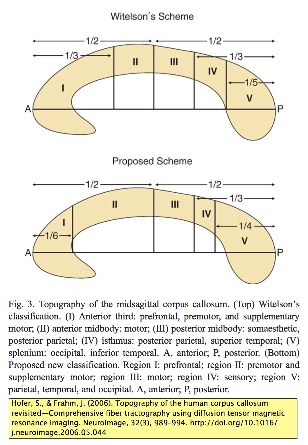
- Divided into three segments after the method of Hofer and Frahm (2006)
- anterior sixth is the genu of CC (gCC)
- posterior quarter is the splenium of CC (sCC)
- ...everything in between is the body of the CC (bCC)
- Define midline slices for each CC segment
- if the head is perfectly straight, each segment has the same midline position
- usually, each segment may have a slightly different midline position
- Use the midline slice of the bCC to calculate the anterior-posterior (A-P) length of the entire CC
- from this slice, the coronal slice positions used to separate each CC segment are defined
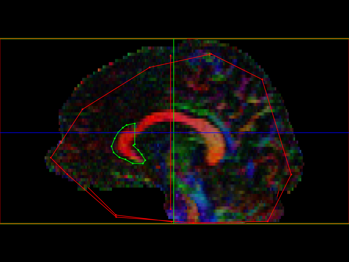
genu of the Corpus Callosum (gCC)
- Midline AND: place ROI on anterior 1/6-th of the CC, on the midline of the gCC.
- Note that for subjects who are slightly rotated, the midline of the entire CC (used to calculate the AP length) might not be the same slice selected to place the midline AND ROI on the gCC
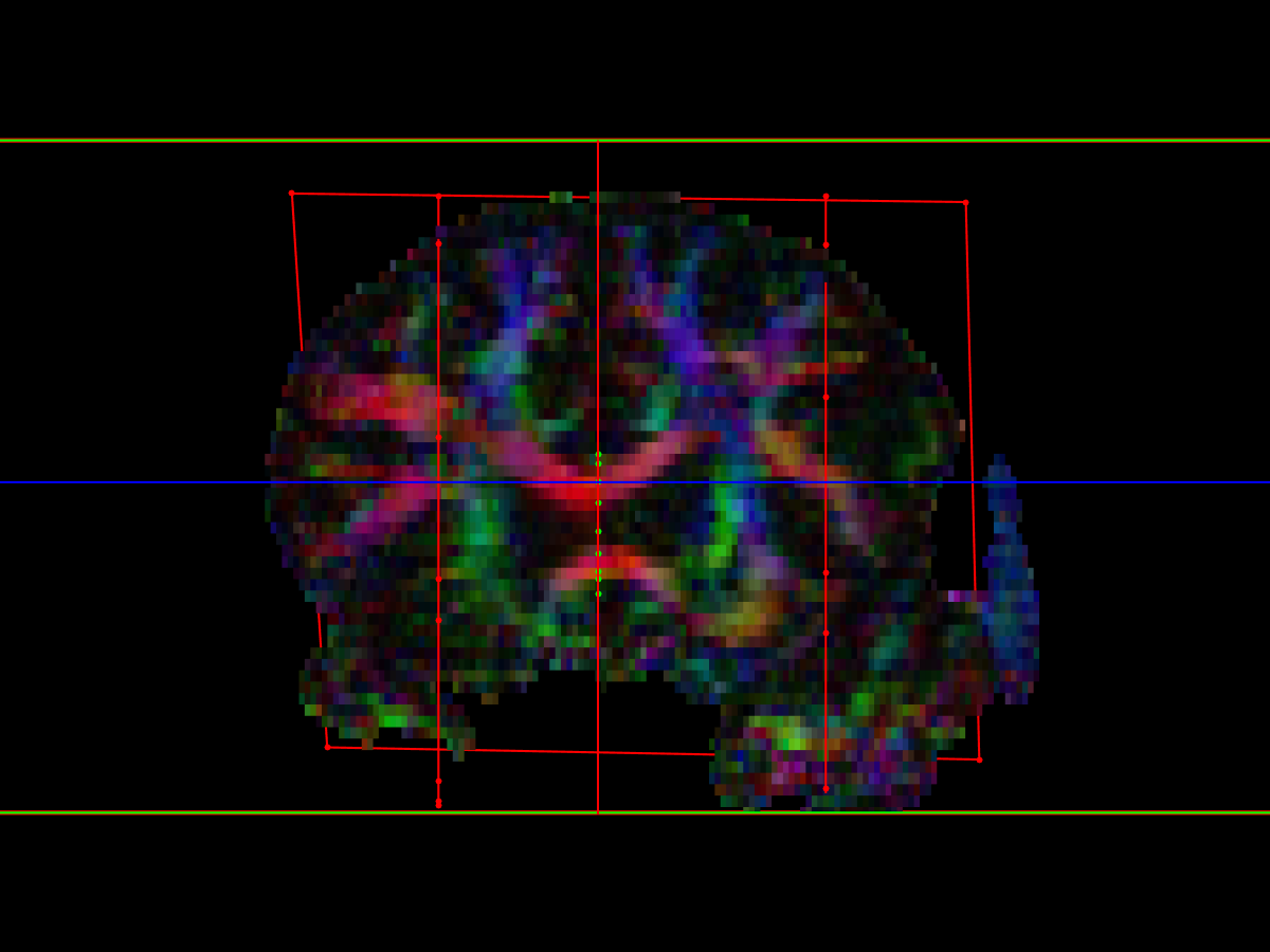
- Parasagittal NOT: two ROIs, placed lateral to the parasagittal AND ROI
- Celi Andrade described this as "count 15 slices (30 mm) from midline, equal both sides, larger than [AND]... exclude lateral projections"
- For our purposes, we have decided to place the NOT ROIs just lateral to the descending cortico-spinal tracts (CSTs), which is roughly the same position, but relies on an anatomical landmark rather than slice-counting
- Coronal NOT: a single ROI place behind the gCC.
- Celi Andrade described this as "coronal plane, exclude AP projections (cingulum), 8 to 10 slices posterior to genu’s posterior edge, surpassing the lateral NOTs"
- For consistency, we have decided to place the coronal NOT ROI at the midpoint of the CC, behind the gCC, with the lateral edges of it just touching the lateral NOTs
body of the Corpus Callosum (bCC)
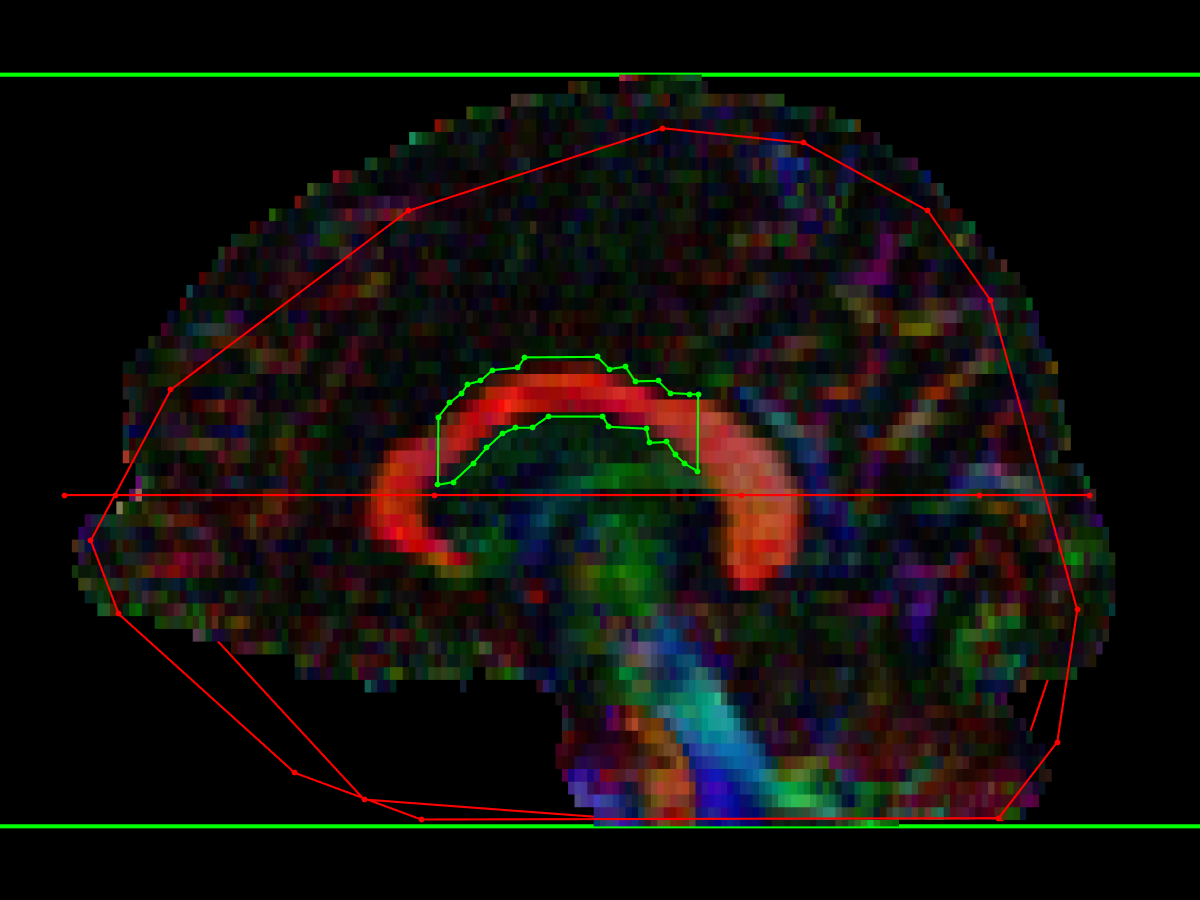
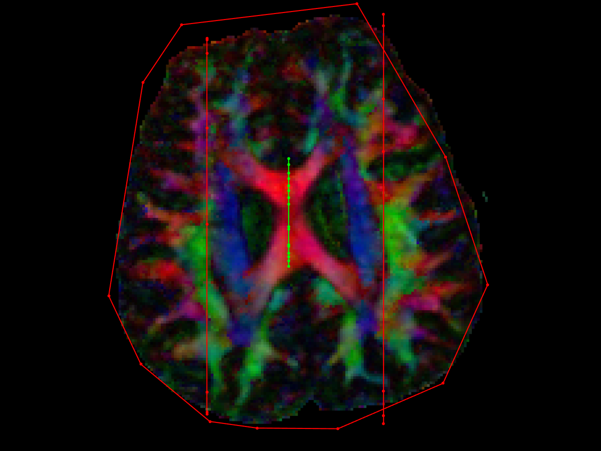
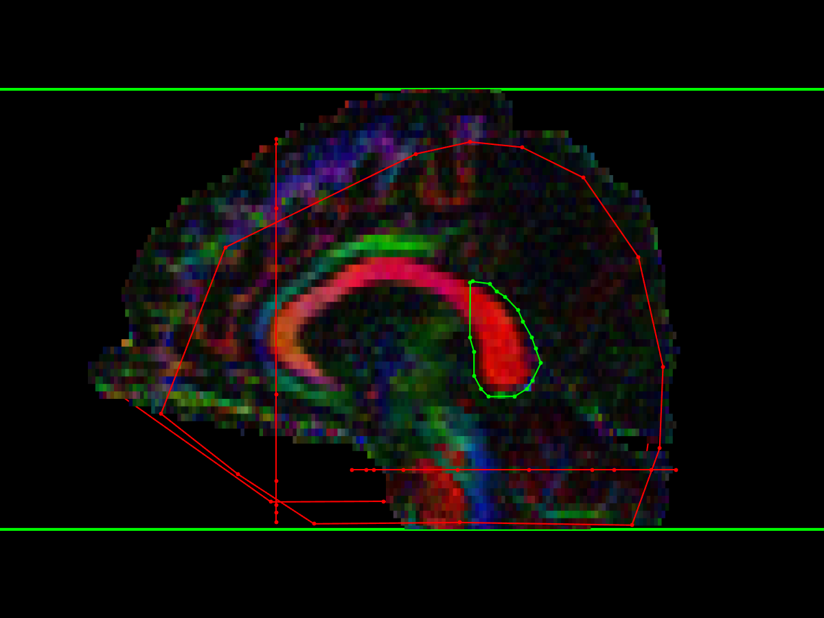
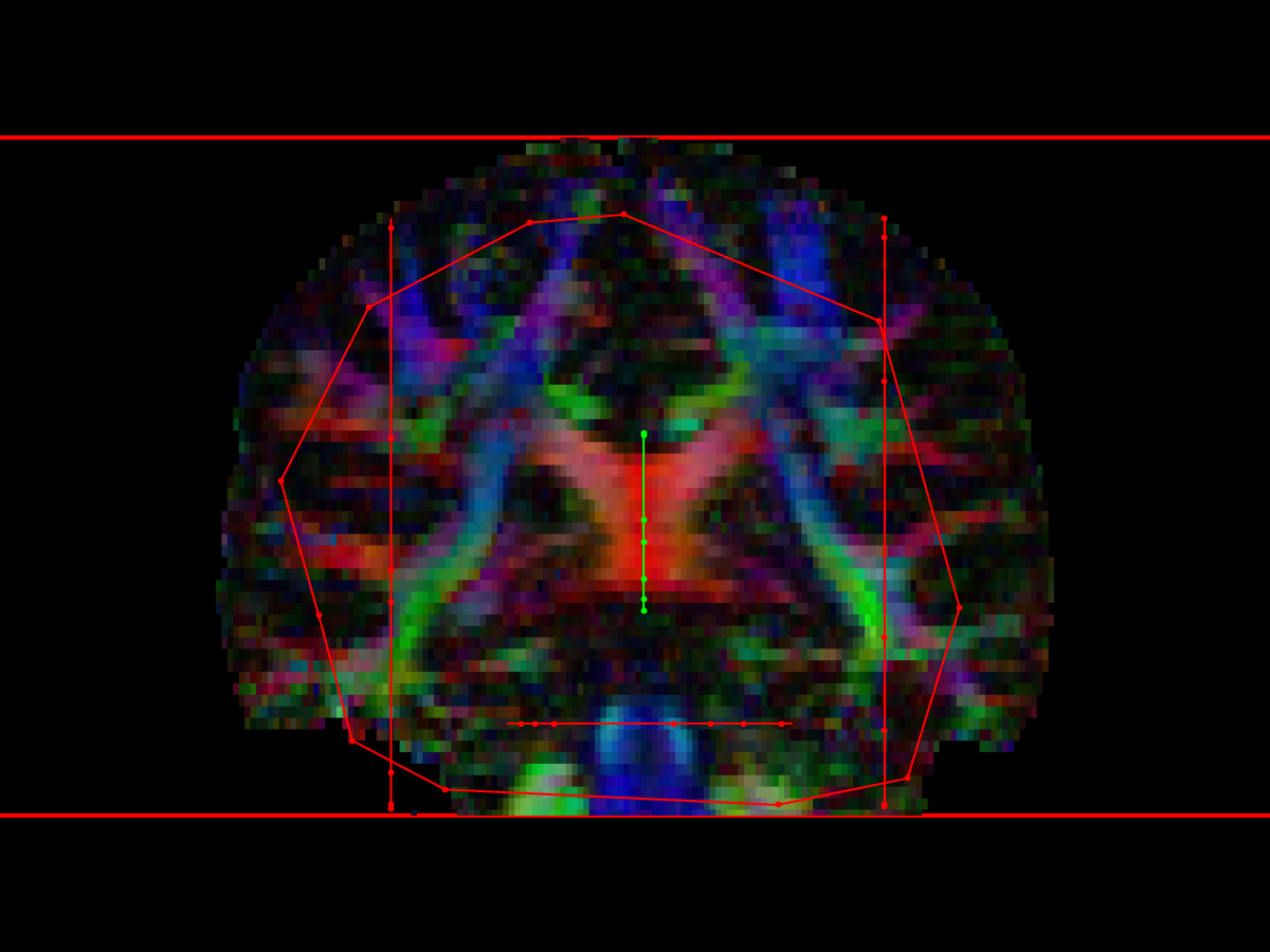
- Midline AND: place ROI on midline of bCC
- I suggest to load the gCC midline AND ROI as a reference to avoid overlap
- Parasagittal NOT: as described for gCC, two parasagittal NOT ROIs placed lateral to the AND ROIs
- Again, Celi placed these 15 slices lateral (15 x 2mm = 30 mm on her scans) to the midline, and lateral to the CST, for our purposes we will aim just lateral to the CST
- These NOT ROIs should be quite large, to exclude lateral projections
- Axial NOT: placed below the CC
- As described by Celi Andrade: "axial slice just beneath the AND ROI, encompassing the lateral ventricles and other ROIs"
- For our purposes, for consistency and ease of use, the NOT ROI encompasses the entire brain, immediately below the AND ROI (which is effectively what Celi was doing, anyway)
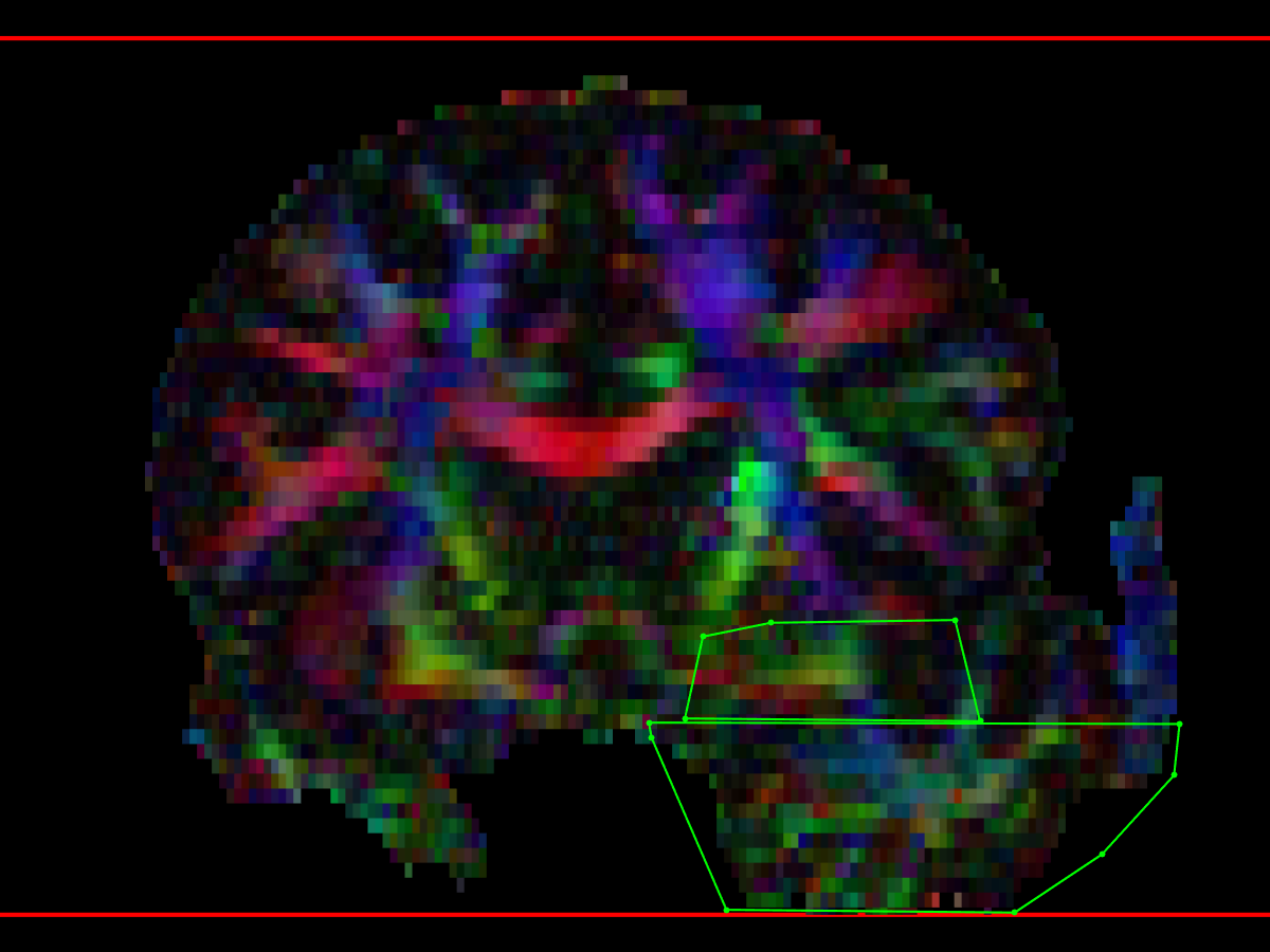
splenium of the Corpus Callosum (sCC)
- Midline AND: placed on midline of sCC
- I suggest to load the bCC midline AND ROI as a reference to avoid overlap
- Parasagittal NOT: as for gCC and bCC, two parasagittal not ROIs, placed lateral to the AND ROI
- As Celi says: "NOT: 19 slices (+/-2) (38 +/- 4 mm) parasagittal (+big heads, lateral to CST, on sagittal pane – SLF bulk)"
- Our method will be to place them lateral to the optic radiations (which roughly corresponds to the distance that Celi used)
- Axial NOT: placed below the AND ROI, to exclude descending tracts, but must not extend into occipital lobes (as this would exclude projections from sCC to the occipital lobe)
- Ehsan and I found this one tricky to define, as Celi's description is confusing: "NOT: axial inferior, tangential to the superior edge (with CST) and centered in the midbrain, including the cerebellum (not entire occipital lobes)"
- We decided to place an axial NOT at the level of the pons, including the entire pons, and any cerebellum at that level, but excluding the occipital and temporal lobes (this is easy to find using the “heavy red bar” on the FEFA maps, corresponding to the horizontally crossing cortico-ponto-cerebellar fibres, to define the level of pons).
- Coronal NOT:
- place it covering the whole cerebrum on the most anterior slice of CC
- Removes spurious tracts to frontal lobes
Corticospinal Tract (CST)
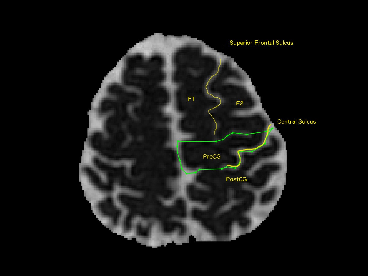
- Cerebral Axial AND ROI
- Based on identification of central sulcus on axial images
- It useful to view non-DWI or MD images to better find the central sulcus
- Identify the following landmarks:
- superior frontal sulcus (SFS) between the superior frontal gyrus (F1) and middle frontal gyrus (F2)
- pre-central gyrus (PreCG) and post-central gyrus (PostCG)
- look for the “upside-down omega” sign of the precentral gyrus which identifies the hand bulb
- central sulcus
- Draw an axial AND ROI around the entire precentral gyrus at the most inferior slice containing a clearly-defined central sulcus
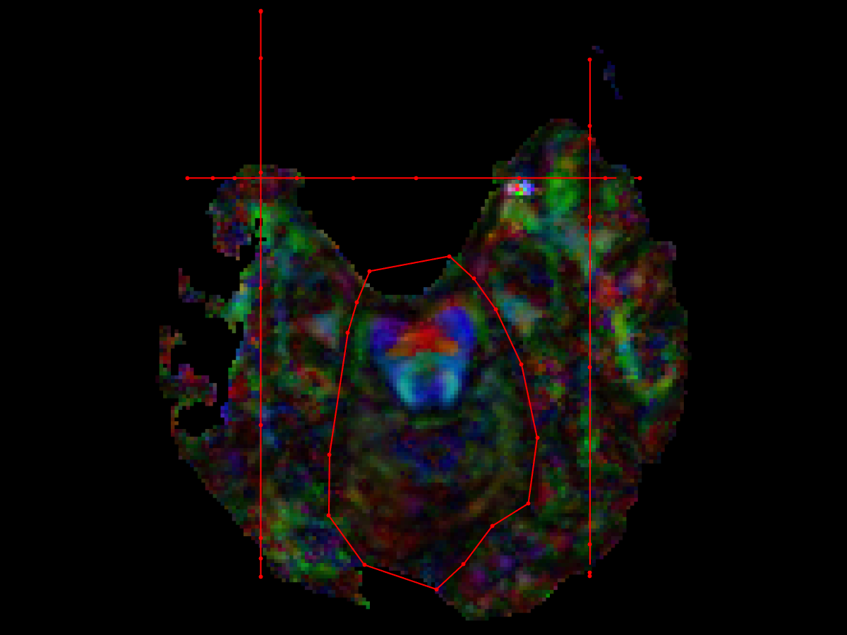
- Midbrain axial AND ROI
- Find the axial slice showing the decussation of the superior cerebellar peduncle (dSCP) in the dorsal midbrain.
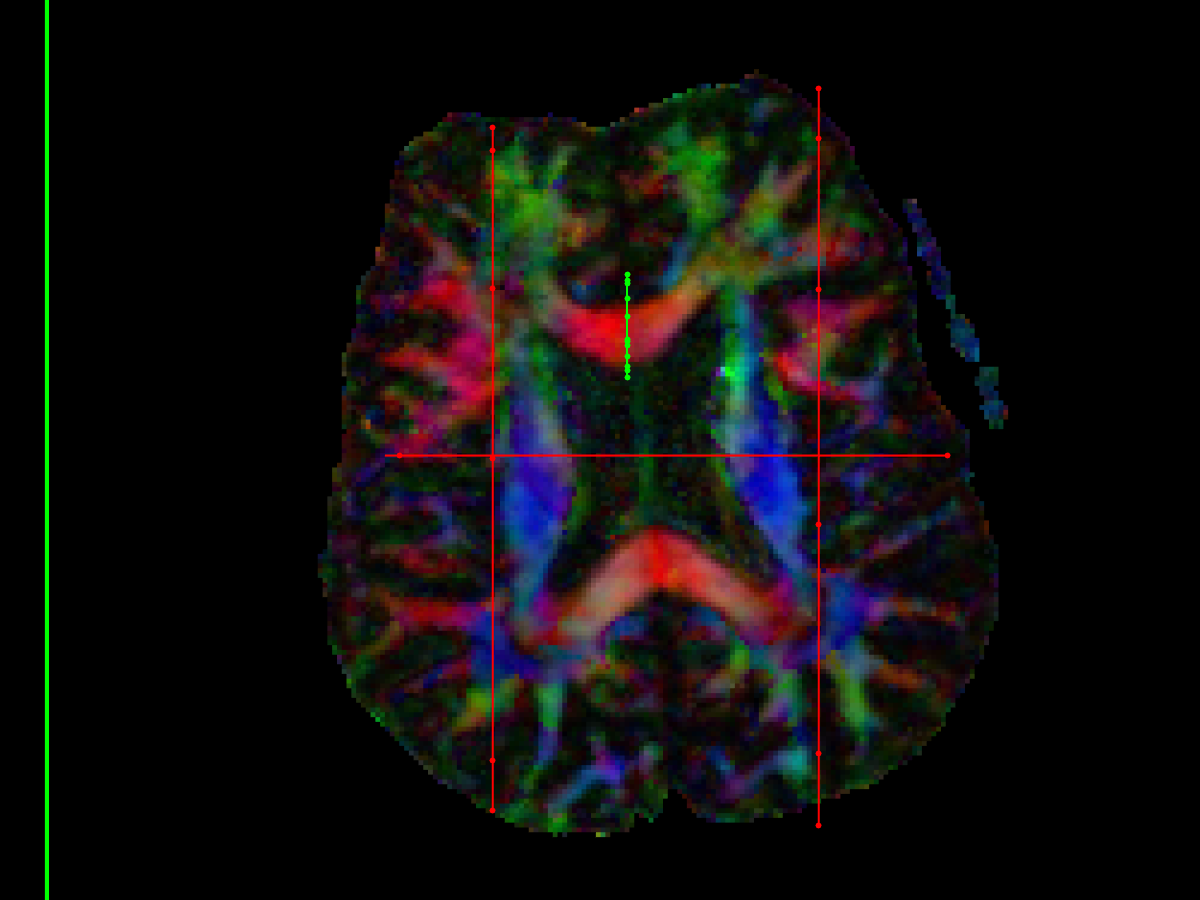
- On DTI images, it's a bright red dot due to the transverse crossing fibres (Nagae-Poetscher et al 2004)
- Draw an AND ROI around the cerebral peduncle on the desired side
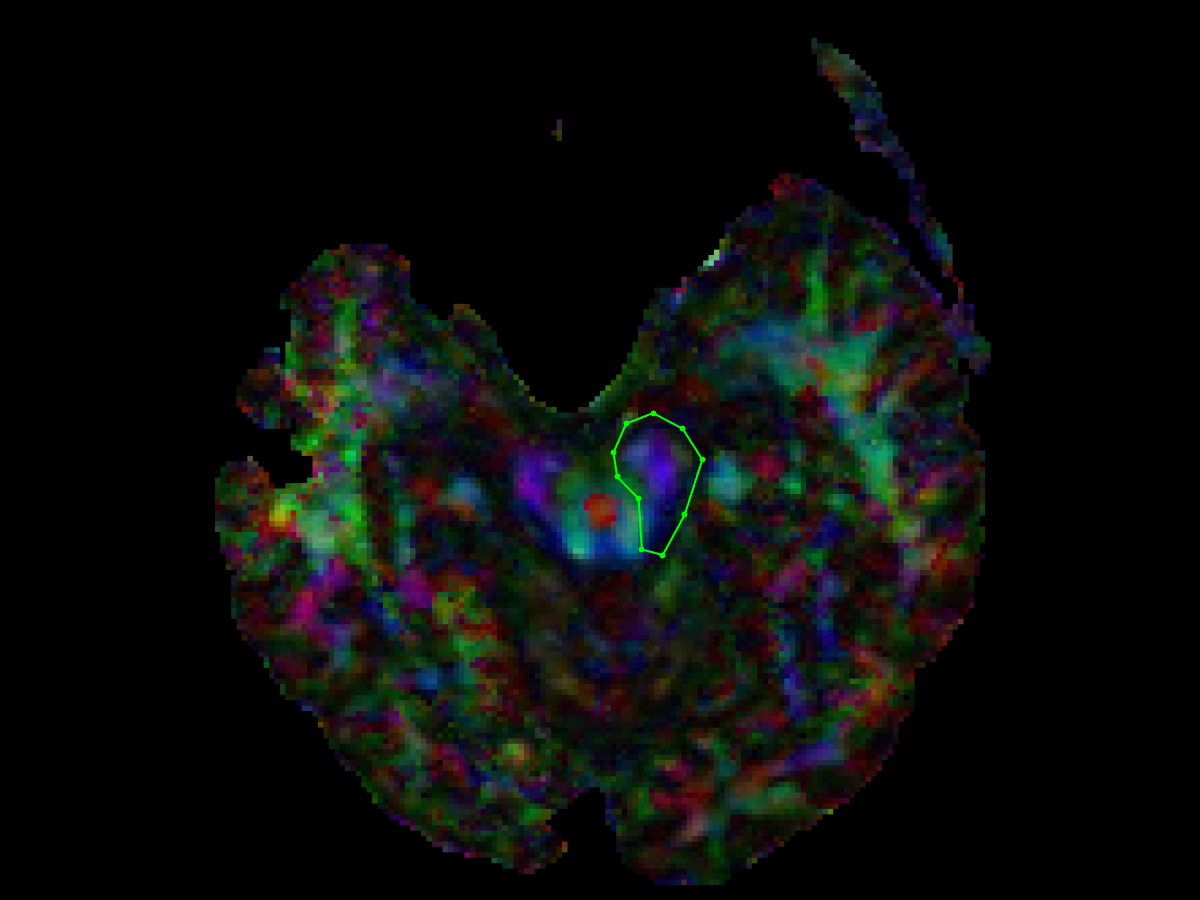
- Pontine axial AND ROI
- Draw the AND ROI at the level of the pons, where the transverse corticopontocerebellar fibres clearly demarcate the ventral descending tracts
- Either or both of the brainstem axial AND ROIs may be applied, depending on the case
- NOT ROIs are applied as needed to remove spurious tracts
- Midline Parasagittal NOT ROI
- just split the whole brain in half, right down the middle
- Coronal brainstem NOT ROI
- to exlcude corticocerebellar projections from ipsilateral primary motor cortex
- placed behind the CST, to exclude anterior-posterior projections into the cerebellum
- Be careful, as the CST often drifts anterior to posterior (or posterior to anterior, depending on head placement), and so NOT ROI must be placed precisely to avoid excluding CST fibres
- Axial NOT ROI – might not be necessary in all cases
- placed at level of pons, posterior to the tranverse (left-right) ponto-cerebellar tract
- Note from Wakana (2007) - "The tracking method described in this protocol usually reconstructs only the CST projecting to the medial cortical regions. The CST projection to the lateral areas of motor cortex cannot be accurately reconstructed because there is a significant mixing of fibers with different orientations within the pixels as the CST passes through the massive bundle of association fibers."
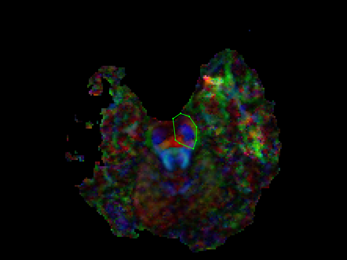
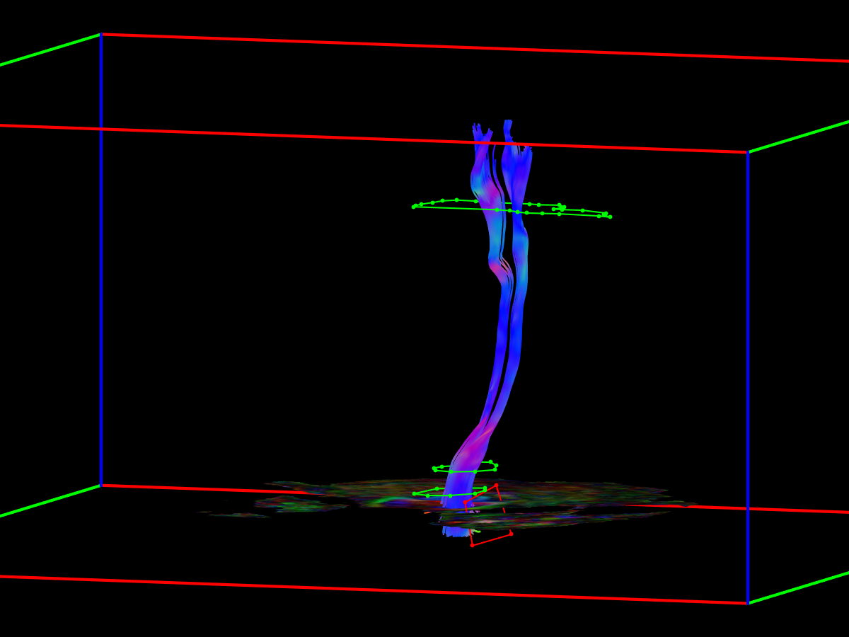
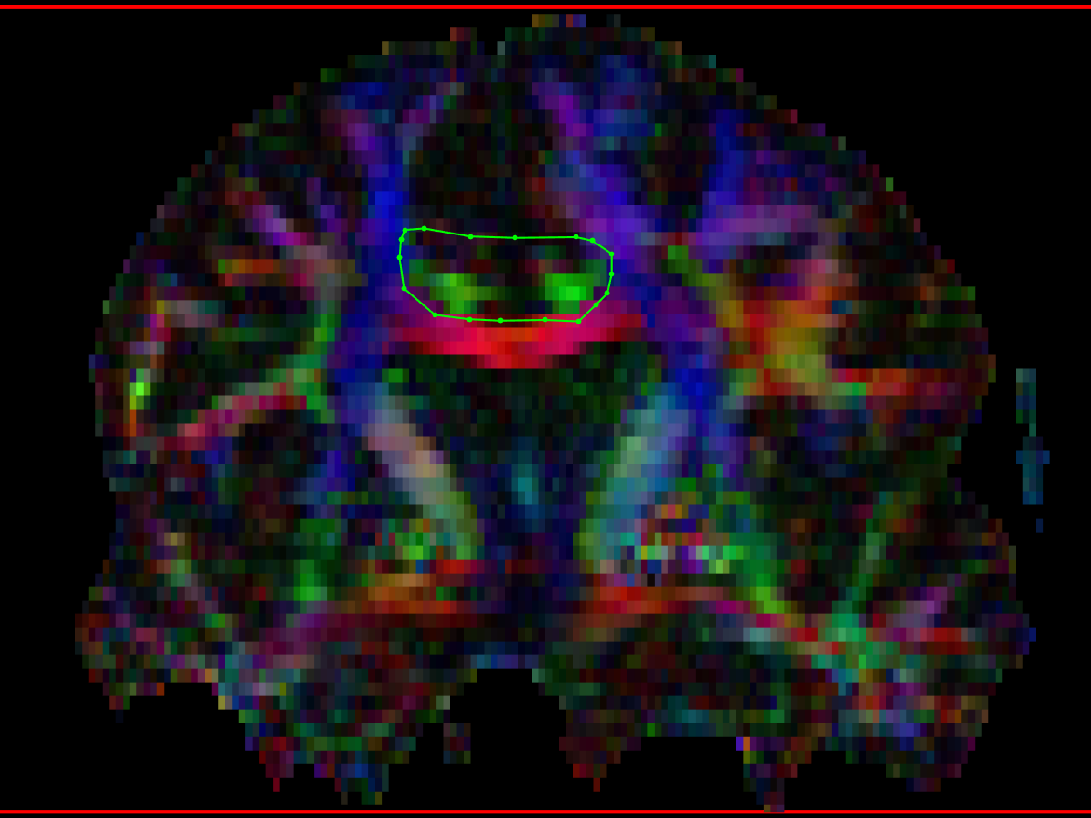
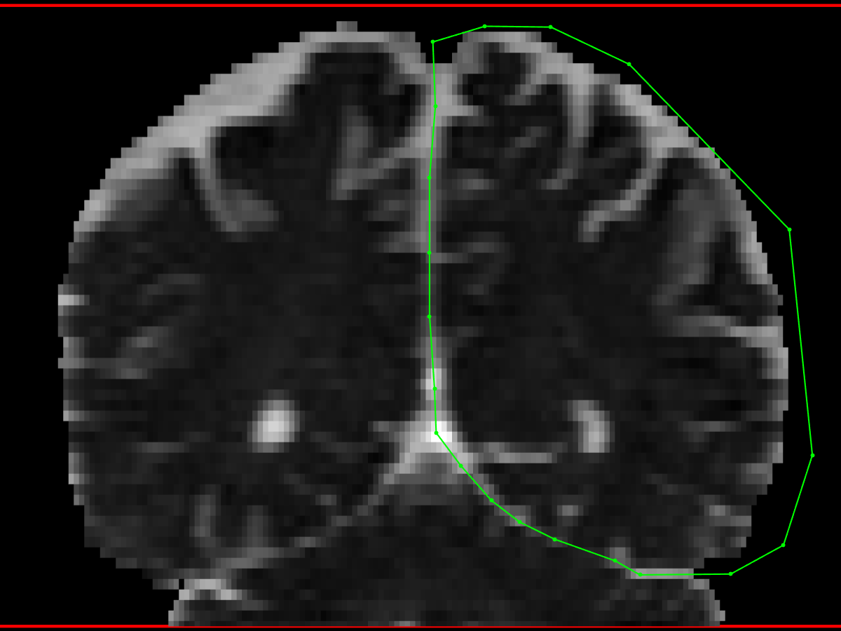
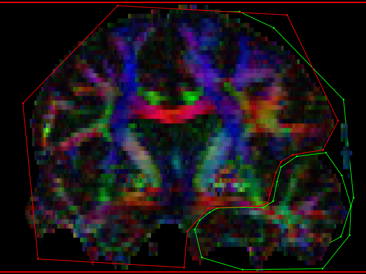
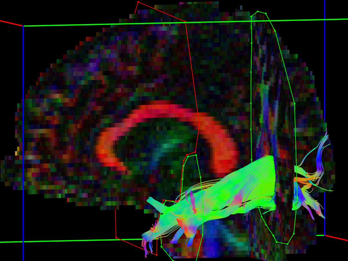
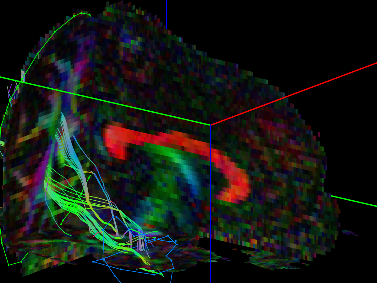
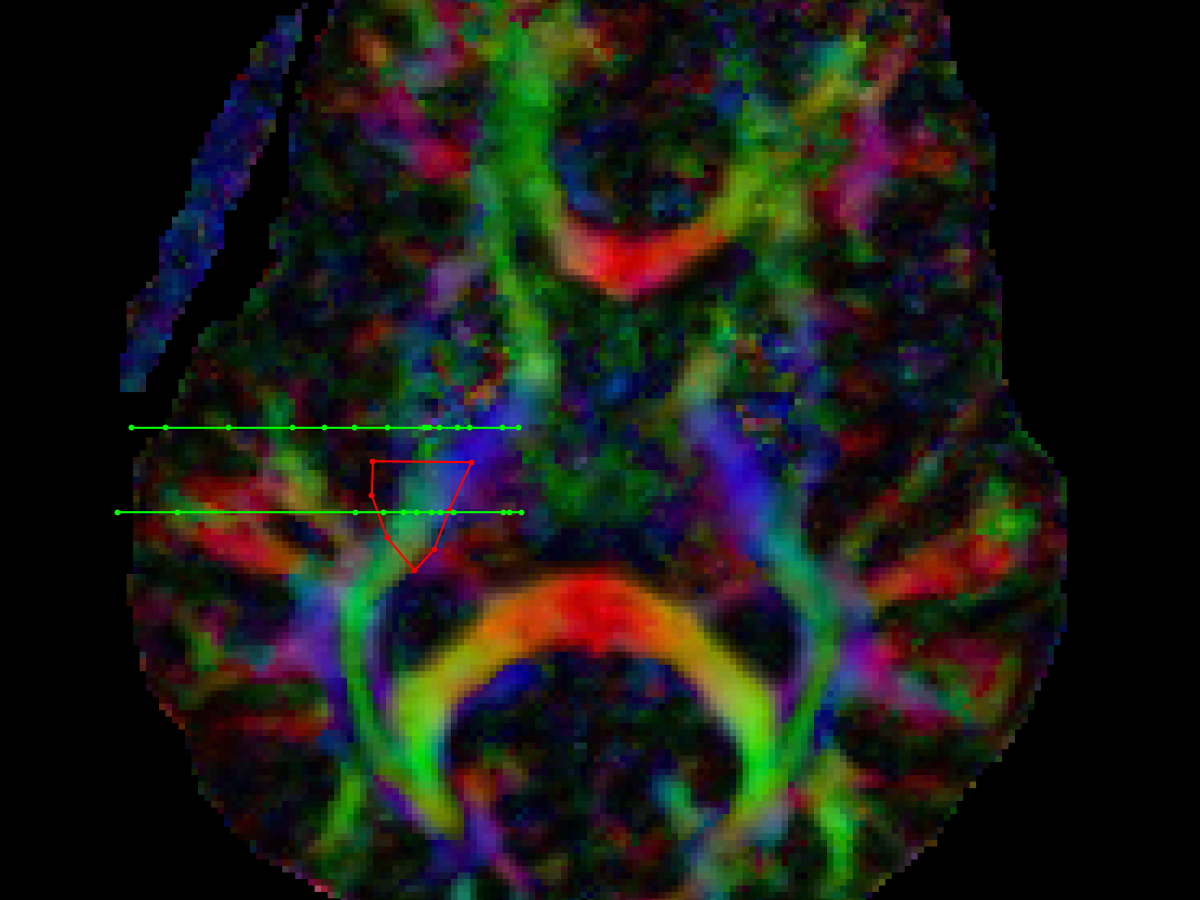
Fornix (Fx)
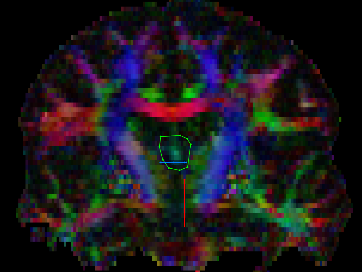
- coronal AND ROI
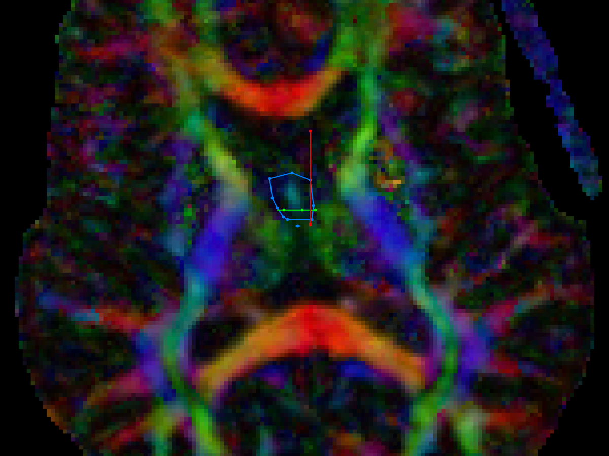
- axial SEED ROI
- placed on column of fornix
- coronal SEED ROI
- placed on body of fornix, posterior to the AND ROI
- various NOT ROIs are placed as needed
- sagittal NOT ROI on the corpus callosum on the midline
- coronal NOT ROIs anterior and posterior to the fornix
- axial NOT ROI above the fornix
- parasagittal NOT ROIs lateral to the column of the fornix (eliminate tracts from anterior commissure)
- note that the crurae of the fornix are difficult to reproduce on conventional DTI images due to their proximity to the ventricles, and resultant contamination by CSF signal
- Concha et al (2005) described a method of FLAIR DTI that produced superior images, but these images were not acquired in this study
- "Because the fornix and cingulum are adjacent to CSF spaces (ie, the ventricles and interhemispheric fissure), the delineation of the tracts and their absolute diffusion parameters may be adversely affected by partial volume with the rapid, isotropically diffusing CSF. The use of a fluid-attenuated inversion recovery (FLAIR) component before a DTI imaging sequence greatly minimizes CSF signal intensity contamination, though at the expense of a significant increase in acquisition time and a reduction in signal intensity–to-noise ratio"
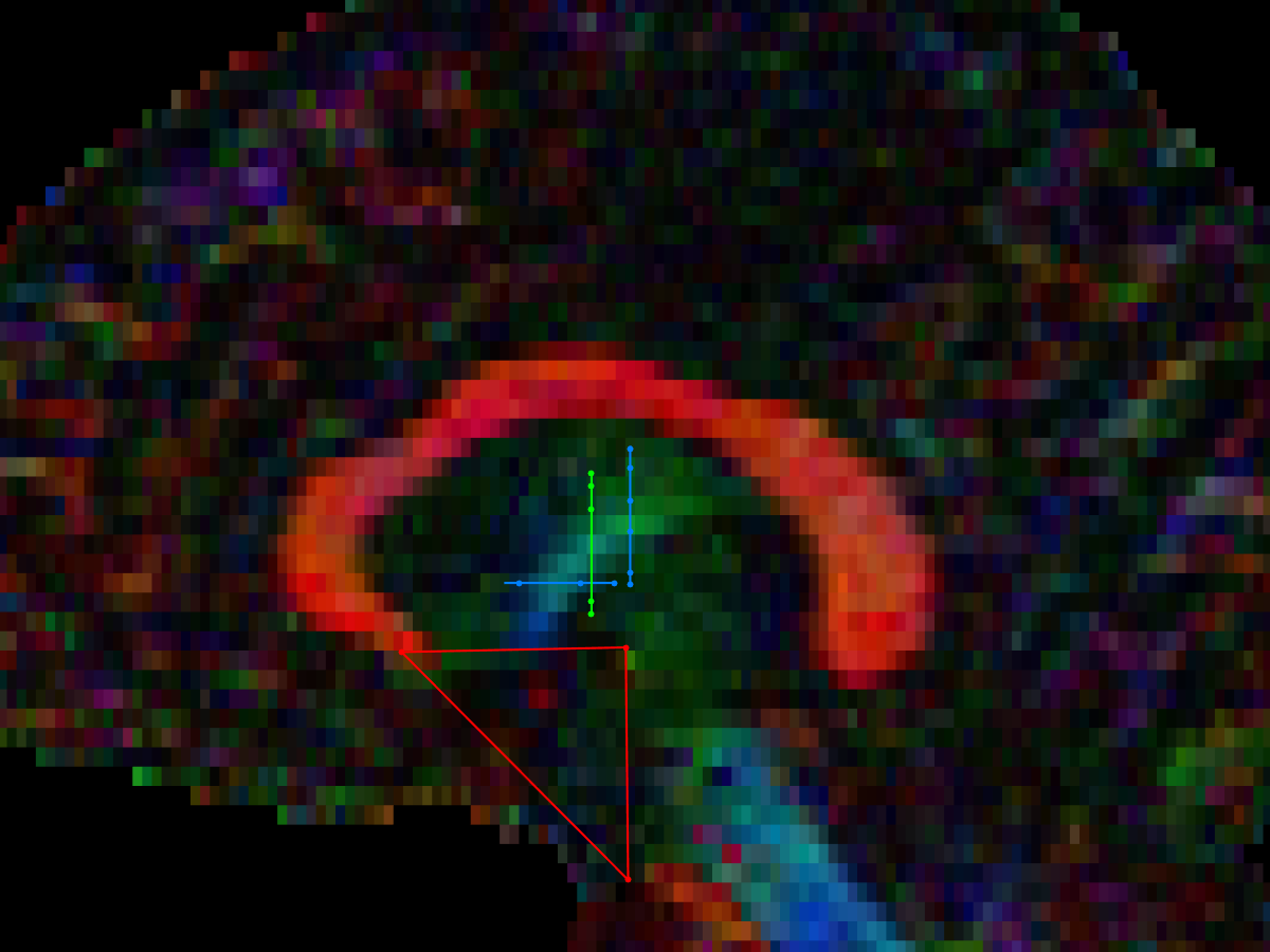
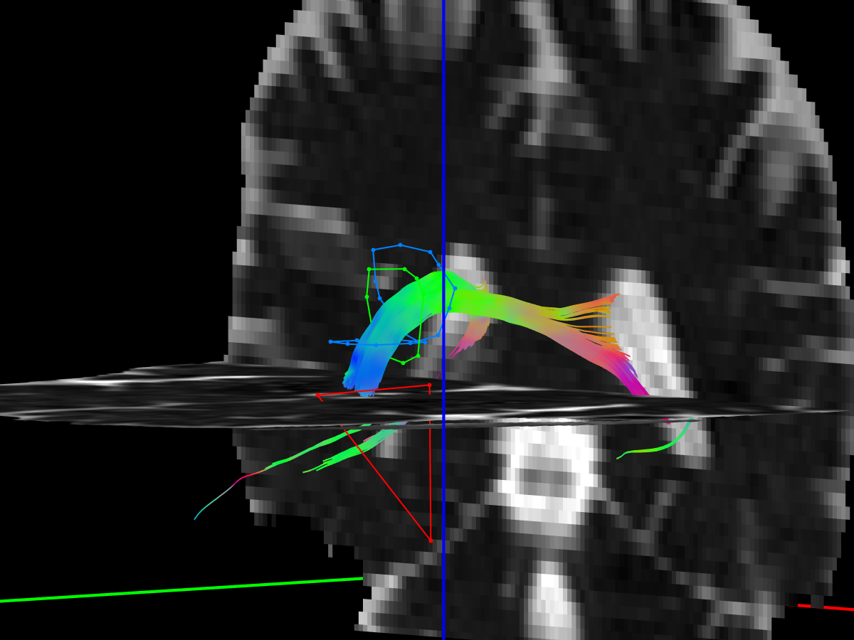
Cingulum
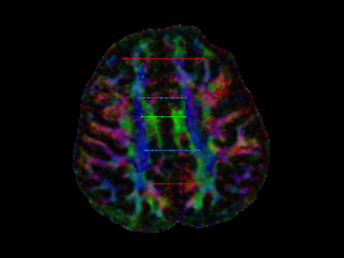
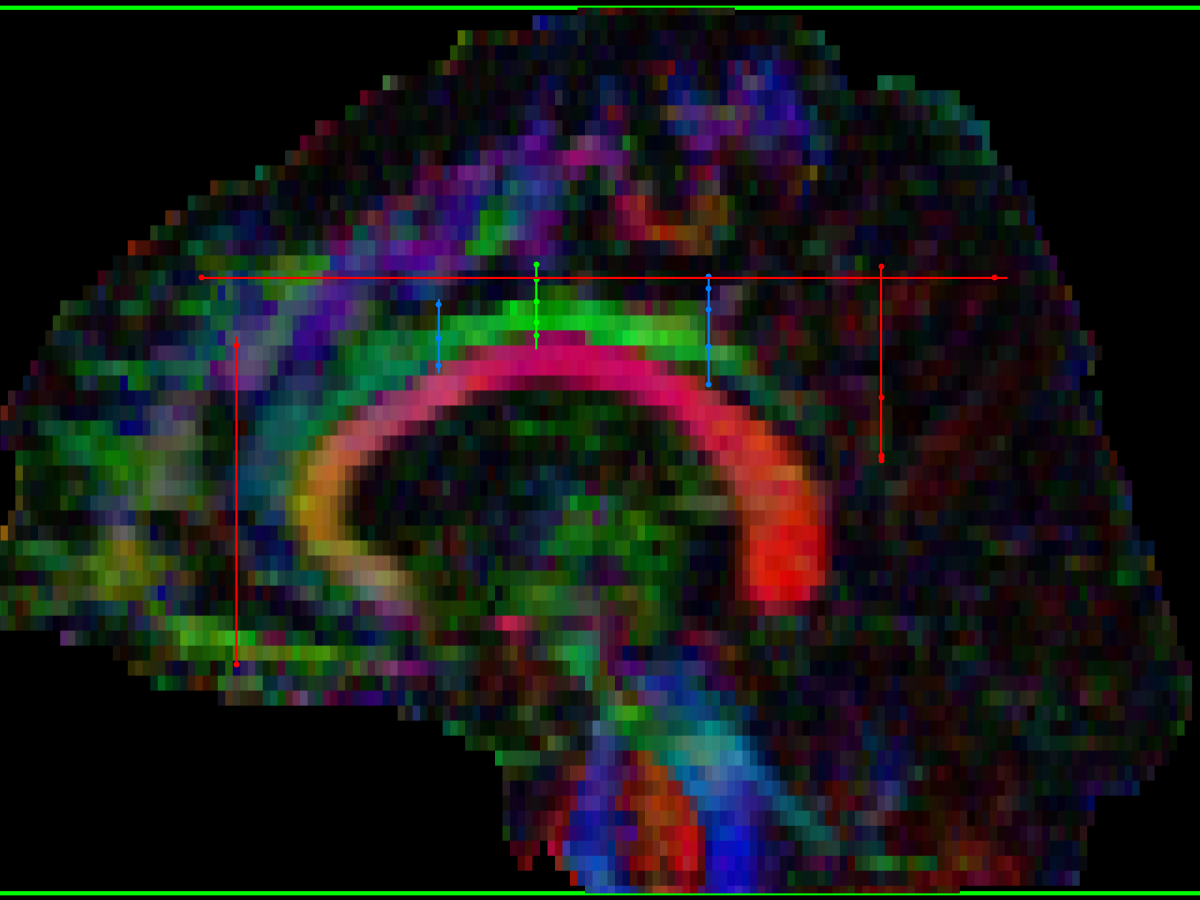
- coronal AND ROI:
- drawn at the mid-point of the superior (dorsal) cingulum, includes both cingulum bundles
- coronal (or axial) SEED ROIs:
- a pair of ROIs, one anterior, and one posterior to the initial AND ROI
- depending on the orientation of the cingulum on an individual scan, these might be drawn in the axial or coronal plane
- various NOT ROIs placed as needed:
- pair of coronal NOT ROIs placed anterior and posterior to the cingulum
- axial NOT ROI placed above the cingulum may be necessary
- ...as noted by Concha et al (2005):
- "Because the fornix and cingulum are adjacent to CSF spaces (ie, the ventricles and interhemispheric fissure), the delineation of the tracts and their absolute diffusion parameters may be adversely affected by partial volume with the rapid, isotropically diffusing CSF. The use of a fluid-attenuated inversion recovery (FLAIR) component before a DTI imaging sequence greatly minimizes CSF signal intensity contamination, though at the expense of a significant increase in acquisition time and a reduction in signal intensity–to-noise ratio"
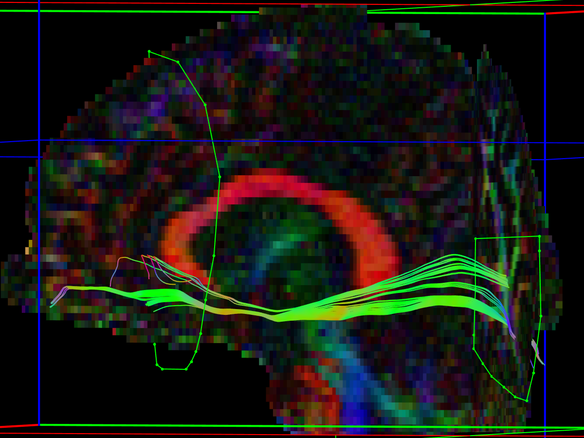
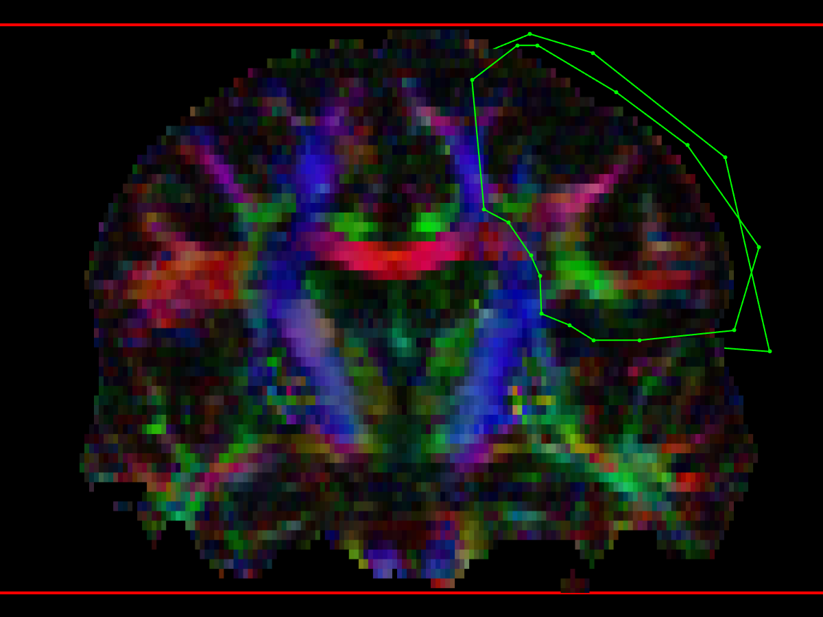
Inferior fronto-occipital fasciculus (IFO)
method from Wakana 2007
- First coronal AND ROI
- On parasagittal view (place on the cingulum)
- Define posterior edge of cingulum
- Define posterior edge of parieto-occipital sulcus (POS) (easier to see on non-DW or MD images rather than FEFA color map)
- Find coronal section on the mid-point between these two planes
- Draw a coronal AND ROI that delineates the occipital lobe at this level
- Define the boundary between the occipital and parietal lobes by extending the POS laterally from the parasagittal slice where it intersects the midpoint coronal AND ROI
- Second coronal AND ROI
- coronal slice is selected at the anterior edge of the genu of corpus callosum (gCC) and the entire hemisphere is delineated.
- NOT ROIs
- placed as needed to remove fibres from the cingulum and some fibers relayed at the thalamus.

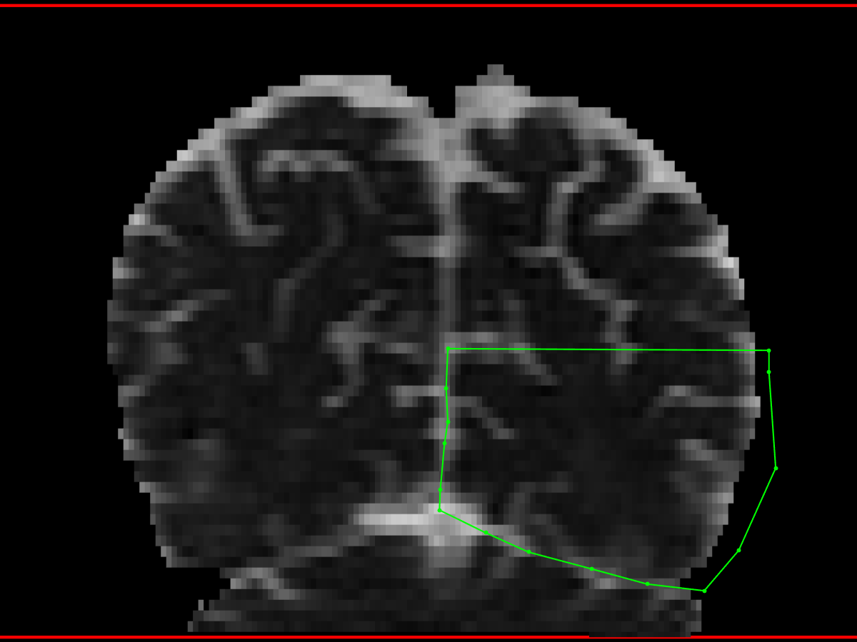

Inferior longitudinal fasciculus (ILF)
method from Wakana 2007
- First coronal AND ROI
- Using a parasagittal slice, the posterior edge of the cingulum (for that side) is identified
- Create an AND ROI that includes the entire hemisphere
- Second coronal AND ROI
- the most posterior coronal slice in which the temporal lobe is not connected to the frontal lobe is selected.
- A little bit tricky to find... try to find the medial posterior margin of the anterior temporal lobe on an axial slice view
- this method tends to place the AND ROI too anterior, missing many ILF fibres, so I have to move posterior using the FEFA (DTI) images to guide to the point where ILF branches off from the IFO bundle
- Be careful not to include the inferior fronto-occipital fasciculus (IFO), which lies above the ILF
- Create an AND ROI that includes the entire (anterior) temporal lobe.
- Optional coronal NOT ROI – to exclude IFO
- sometimes it is difficult to exclude the IFO from the ILF using the AND ROIs
- in that case, place a coronal NOT ROI, either:
- anterior to the corpus callosum (CC), covering the whole frontal lobe – analogous to the second coronal AND ROI used to define the IFO
- or in the same plane as the second coronal AND ROI, excluding everything outside of the AND ROI (I find this works better)
- Axial SEED ROI
- This method is needed in cases where the angle of the scan acquisition has caused the inferior portion of the anterior temporal lobes to be lost (in which case the second coronal AND ROI captures very few tracts)
- The second (anterior) coronal AND ROI is replaced with a SEED ROI in the same position
- The axial SEED ROI is drawn from the anterior tip of the temporal pole, extending posterior to roughly the posterior margin of the hippocampus (or the midbrain could be used as a reference)
- The disadvantage to this method is that there may be numereous non-ILF tracts included as well, and several coronal NOT ROIs are needed to be included to eliminate them.
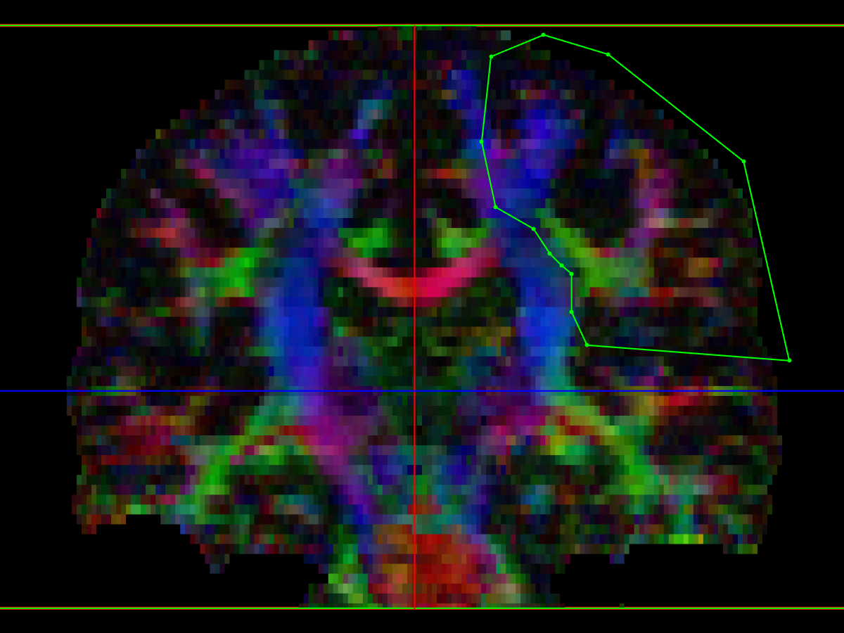
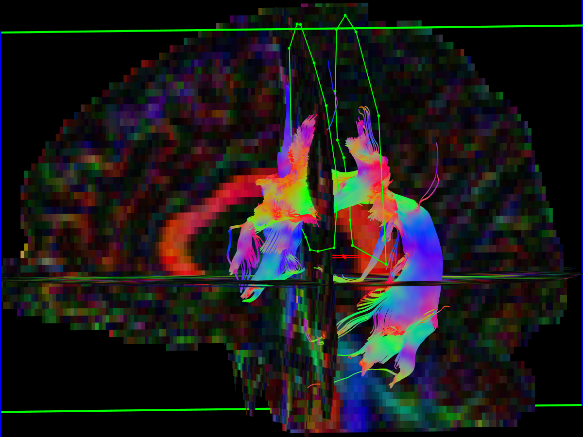
Superior longitudinal fasciculus (ILF)
method from Wakana 2007
- First coronal AND ROI
- placed so that it intersects the mid-point of the posterior limb of internal capsule
- select the anterior-posterior (green) fibres of the SLF, located lateral to the CC and CST
- Second coronal AND ROI
- placed on a coronal image at the posterior margin of the sCC on midline
- select the anterior-posterior (green) fibres of the SLF
- Note that the locations for the coronal slices above should serve only as a guide... it's best to roll back-and-forth 5-10 slices from each landmark location, and then choose a slice on which the SLF appears as a tight, coherent, green triangle.
- axial NOT ROIs may be needed to exclude the descending CST tracts
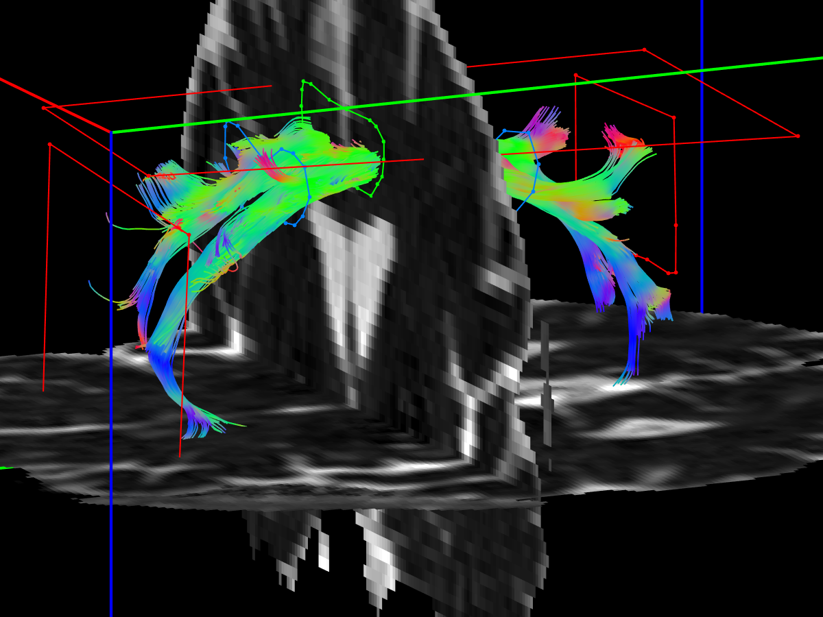
Uncinate fasciculus (UF)
method from Malykhin 2008
- First axial AND ROI
- on axial view, identify the vertical (inferior – superior, blue) coursing UF fibres in the anterior temporal lobe, just lateral to the amygdala
- draw a nice big AND ROI around it - it's OK to be "greedy" with this one
- Second and third axial AND ROIs
- on a coronal view, advance to the anterior edge of the axial AND ROI
- on this view, the frontal lobe and anterior temporal lobe should both be visible
- place second AND ROI below the first, including all fibres of anterior temporal lobe
- place third AND ROI above the first, including fibres of the inferior frontal lobe
- May need a single coronal NOT ROI posterior to the UF


References
- Andrade, C. S., Leite, C. C., Otaduy, M. C. G., Lyra, K. P., Valente, K. D. R., Yasuda, C. L., et al. (2014). Diffusion abnormalities of the corpus callosum in patients with malformations of cortical development and epilepsy. Epilepsy Research, 108(9), 1533–1542. http://doi.org/10.1016/j.eplepsyres.2014.08.023
- Concha, L., Gross, D. W., & Beaulieu, C. (2005). Diffusion tensor tractography of the limbic system. AJNR American Journal of Neuroradiology, 26(9), 2267–2274.
- Hofer, S., & Frahm, J. (2006). Topography of the human corpus callosum revisited—Comprehensive fiber tractography using diffusion tensor magnetic resonance imaging. NeuroImage, 32(3), 989–994. http://doi.org/10.1016/j.neuroimage.2006.05.044
- Malykhin, N., Concha, L., Seres, P., Beaulieu, C., & Coupland, N. J. (2008). Diffusion tensor imaging tractography and reliability analysis for limbic and paralimbic white matter tracts. Psychiatry Research: Neuroimaging, 164(2), 132–142. http://doi.org/10.1016/j.pscychresns.2007.11.007
- Nagae-Poetscher, L. M., Jiang, H., Wakana, S., Golay, X., van Zijl, P. C. M., & Mori, S. (2004). High-resolution diffusion tensor imaging of the brain stem at 3 T. AJNR American Journal of Neuroradiology, 25(8), 1325–1330.
- Wakana, S., Caprihan, A., Panzenboeck, M. M., Fallon, J. H., Perry, M., Gollub, R. L., et al. (2007). Reproducibility of quantitative tractography methods applied to cerebral white matter. NeuroImage, 36(3), 630–644. http://doi.org/10.1016/j.neuroimage.2007.02.049