Lecture 35: Diffraction: Single slit
Readings: Textbook pages 1234-1243
Diffraction: bending of light around the obstacles
- Diffraction is a spreading of light around the edges of
obstacles.
- Diffraction is a manifestation of the wave nature of light
- Clearest explanation of diffraction is using viewing
wave propagation according to Huygen's principle: each point disturbed
by the advancing wave front can be viewed as a source of a spherical wave,
new front is enveloped of these secondary spherical wave fronts
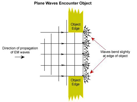
- We have already used Huygens principle to describe phenomenon of
bending of the light ray on interface between media with different
refractive index but it also tells that the light will propagate
behind the obstacles - diffract
| Refraction |
Diffraction |
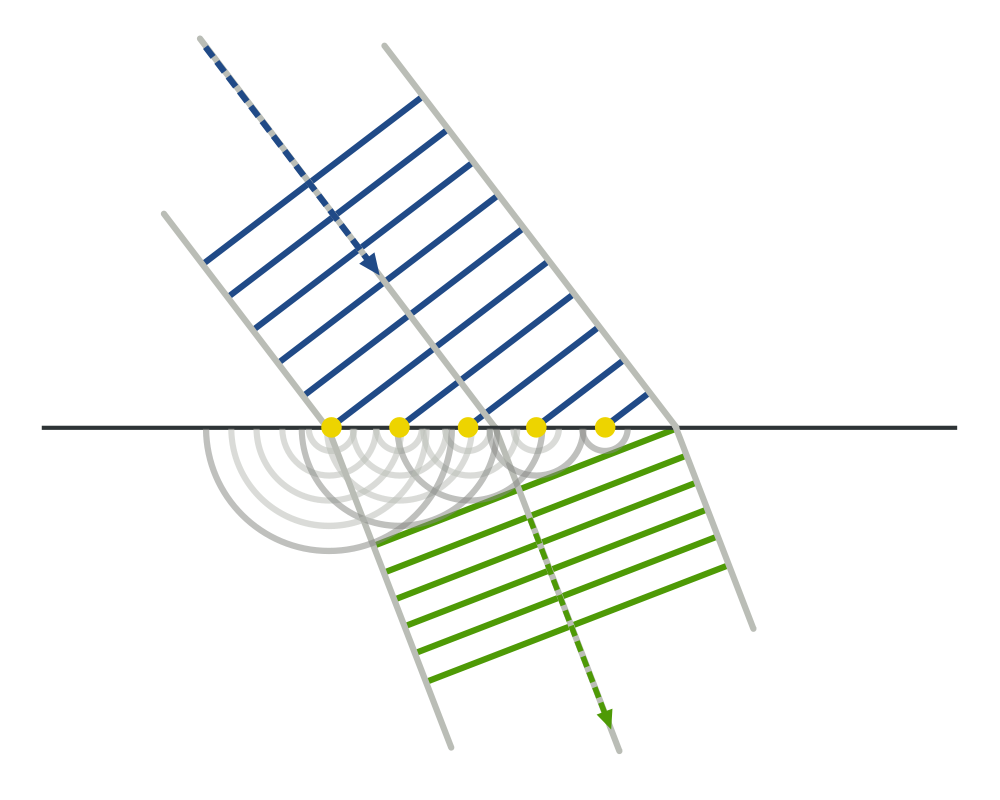 |
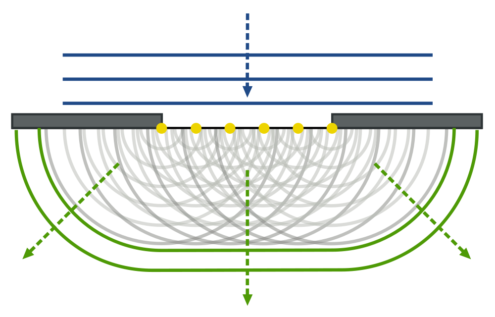 |
- We have used diffraction before to create two coherent sources of light
by a wave passing through two holes.
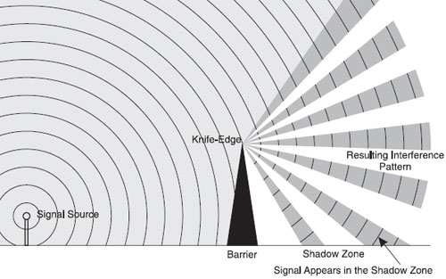
Diffraction and interference
- Outcome of diffraction is not simple.
Diffraction leads to intersecting rays of light, which are coherent and
interfere.
- Interference pattern formed by the diffracted light is
called, for short diffraction pattern
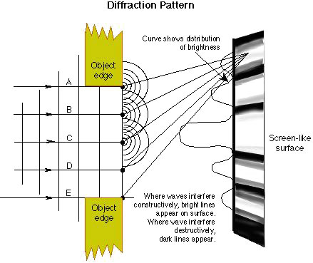
- Sometimes it is emphasized that we speak about diffraction picture
when we consider interference from many sources - as for example
continous distribution
of sources between the barriers in the Figure above.
- Note: Diffraction and interference are different phenomena (despite
what textbook says :) )
Single slit diffraction
- One of the most important examples of diffraction effects is
the passage of light through a hole of finite size.
- If light passes through narrow, point like hole, almost exact spherical
wave forms. However if the hole has a finite size, an interference pattern
forms behind the hole
- We shall consider narrow (but finite width) slits, rather than round
holes. The wavefronts that are formed by the slit are cyllindical rather
than spherical
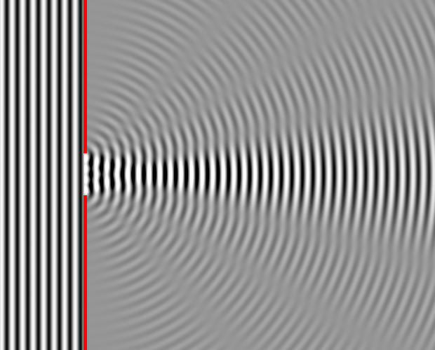
Single Slit Diffraction Applet
- Note that the interference patern of diffracted light from a wide slit
although has geometrical similarity to two narrow slits, is guite different
from as far as intensity distribution is concerned (see for example much
brighter central fringe)
- We shall compute the distribution of the intensity at the screen beyond
the slit.
- The pattern near the slit, where exact wavefront profiles are important
are called near-field, or Fresnel, diffraction . The pattern at the screen far away,
where we can use geometrical optics rays and approximations we have done
in intereference studies is called
far-field, or Fraunhofer diffraction
- We shall consider exclusively the far-field, Fraunhofer, diffraction
pattern.
Intensity in Fraunhofer diffraction pattern from a single slit
- I will replace several pages of discussion in the text book
(but read them) which avoids mathematics with one line calculation
using a simple integration.
- Just to illustrate that often mastering advanced mathematics makes
things easier - thats what for it is introduced in the first place,
actually.
- Resulting pattern is the sum of the waves from every point in
a slit.
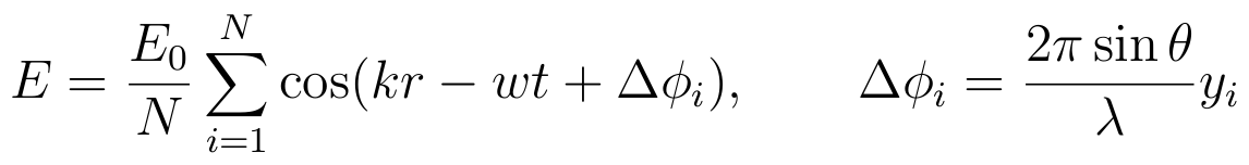
- With continous distribution of source points, it is an integral
over position of a point in a slit y
If the center of a slit has the coordinate y = 0 and
the width of the slit is a, then y varies from
-a/2 to a/2


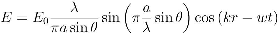
- So we have for the amplitude
- and, finally, for the intensity
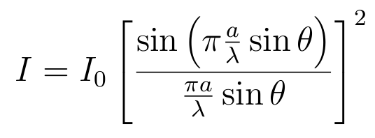
- Here is how it looks like
Minima of Intensity in Fraunhofer diffraction pattern from a single slit
- This is simple, minima is achived at observation angles θ
where sin(π(a/λ) sinθ) vanishes, i.e
sin(θmin) = ±m λ/a
- but not for m = 0 , only for m = 1, 2 ...
- The separation between minima widens when the wavelengths increases or the slit width decreases
- This is why when slit is very narrow a ≈ 0 , the first
minima is far away and one has continous distribution of light.
- sinθ varies from -1 to
1 with zero achieved straight ahead of the slit.
Thus, the number of minima observed is
nmin = 2 int(a/λ)
- If slit is narrower than the wavelength, a < λ,
no minima are observed.
Maxima of Intensity in Fraunhofer diffraction pattern from a single slit
- The main maxima of intensity is at θ = 0
(yes, zero divide by zero gives one here ! )
- Because main maximum is where minimum is expected to be for m=0, it is twice wider than other maxima, occuping space between minima
at ± λ/a . It's width in terms of sinθ is
2 λ/a
- Positions of other maxima are only approximately halfway
between the minima
sin(θmax) ≈ ± (m + ½) λ/a
- Depending on m we speak about first order (m=±1),
second order (m=±2) etc. maxima
- The approximate value of peak intensity at the maximum m > 0 is then
Im ≈ I0 / ( π2 (m + ½)2)