Lecture 34: Interference in Thin Films


Readings: Textbook pages 1218-1223

Thin film interface, monochromatic source, near vertical incidence

Note: in the formulas below, the wavelength &lambda is the wavelength in the film
Arrangement of Layers Phase difference Δφ Interference Condition Application
n1 < n2 < n3 4π t/λ Destructive: t/λ = ½ m + ¼ Anti-Glare coating;
oil films
Constructive: t/λ = ½ m Reflective coating;
oil films
n1 > n2 > n3 4π t/λ Destructive: t/λ = ½ m + ¼
Constructive: t/λ = ½ m
n1 < n2 > n3 4π t/λ - π Destructive: t/λ = ½ m Soap films
Constructive: t/λ = ½ m+¼
n1 > n2 < n3 4π t/λ + π Destructive: t/λ = ½ m Thin layer of air, Newton Rings
Constructive: t/λ = ½ m+¼

Broad Band Spectrum (natural light, thermal sources)

  • Interference occurs only when the film is thin
    2 t < Δ f / f
  • Different wavelength interfere differently

Amplitudes of the reflected light

  • How complete is interference in thin films depends on the amplitude of the light reflected from the upper and bottom surfaces. If they are equal, interference is complete, and in case of destructive setup one has no reflected light
  • What part of light is reflected and what is transmitted at an interface depends on refractive index difference and angle of incident light. When incident light with amplitude E comes close to the normal (perpendicular to the surface), the reflected light has the amplitude
    Er = E (n1 - n2)/(n1 + n2)
    and the transmitted light has the amplitude
    Et = E (4 n1 n2)/(n1 + n2)2
    so that the sum of intensities of the transmitted and the reflected light is equal to the intensity of the incident light
    Ir + It = I
  • It is fun to compute what is the amplitude of light that was reflected from the bottom surface of the film ! (by using this rule several times at each encountered interface)

Full calculation: Angled observation, multiple reflections


Film of variable thinkness

Developed as Oil film interferomentry as used, for example, in aircraft manufacturing


Thin (air) wedge - variable widths layer


  • Use the formulas above
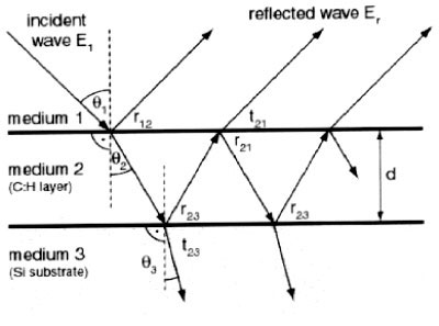
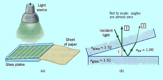
    • Air between glass panels, n1 > n2 < n3 :
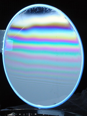
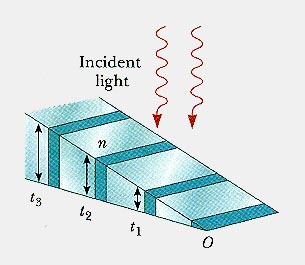
    • Glass wedge illuminated from above, n1 < n2 > n3 :
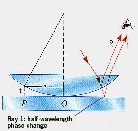
    • Dark fringes where t = x h /l = ½ m λ , hence at x = ½ m ( l λ / h)
    • The end point, x = 0 is dark
  • Think about setup to make the end point bright
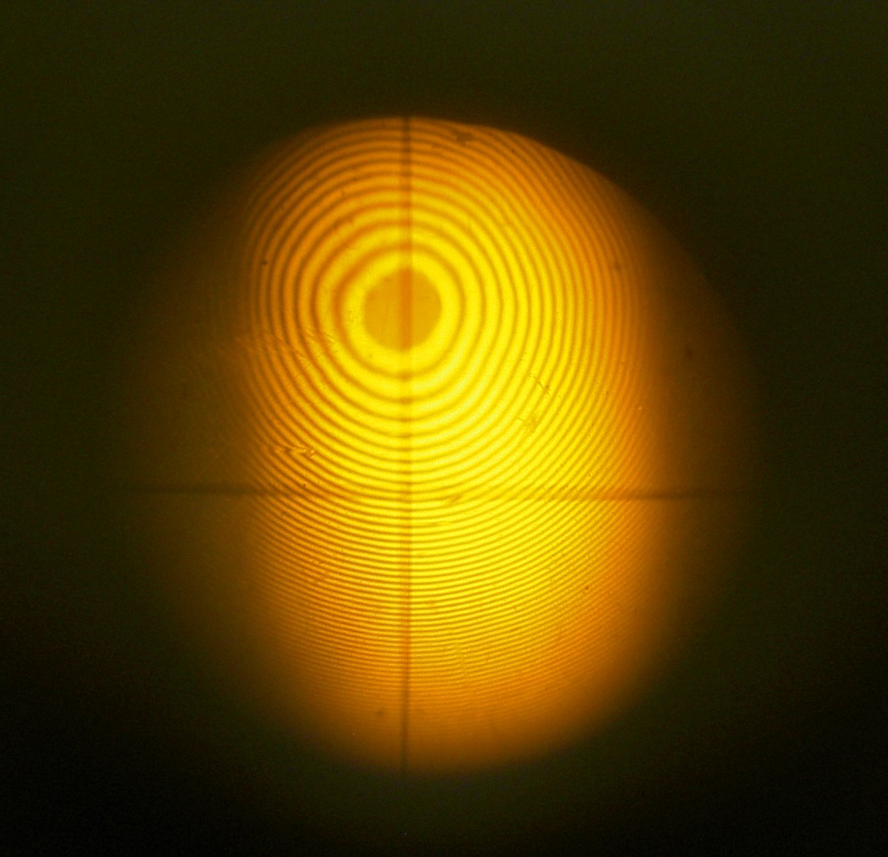
  • Measuring distance between fringes one can determine the wavelength &lambda of light

Thin layer of of air: Newton Rings

Click to expand
  • Exact description of fringes require a bit of trigonometry
  • Measurement of the distance between fringes one can determine, and correct for, the accurate shape of the length
  • Used in lens design, for example for telescopes (well, modern telescopes use mirrors, not lenses)