Welcome to Vacuum Forming
For Solid Scale
=======================================================VACUUM FORMING For SOLID SCALE
Preliminary Draft for Solid Model Memories Cliff Strachan Winnipeg, 2006.
Introduction
Solid Scale Models - carved wooden and generally "scratch-built" miniatures of aircraft -have been used in every capacity from prototypes of design-stage aircraft to wind tunnel test models; from military aircraft recognition models to travel agency, manufacturer and airline promotional materials; from movies to museums, and; from ground schools to commercial kits for both the young and adult.
The prime of Solid Scale kits represented by the 1936 Comet kit of The China Clipper featured a hollow fuselage and four hardwood ready-made engines. In Canada, during the early war years, kits - consisting of a 3view plan, a block of balsa from which the aircraft body was to be carved and thinner pieces of balsa to be used for the wings and tail surfaces - were offered by Easybuilt and Model Craft. As the war proceeded balsa became unavailable. In its place there was presented a block of unyielding hardwood and cardboard.
If this did not initiate the decline in interest in Solid Scale then the highly detailed, realistic but comparatively effortless and less time-consuming plastic kit models of the post-war era certainly completed its demise, ultimately coming to dominate the hobby.
However, such Internet sites as Solid Model Memories and Kenny's Old Time Model Magazine - together with similar sites and their related links - indicate that there exists still, in spite of the requirement for a more arduous commitment and possible deficiencies in realism, a vibrant and expanding universal enthusiasm for the traditional form. If the lack of realism is the main contributor to the decline in interest in Solids and it is accepted that this fault is mainly with respect to "transparencies" - windows, canopies - then by using plastic moulded canopies this deficiency will be mostly eliminated.
Here then is an attempt to present a simple Vacuum Box so that Solid Scale modelers may address this problem: to build plastic canopies and achieve the highest level of realism attainable. The Vacuum Box is not claimed to be entirely unique: a box is a box as a wheel is a wheel. Its principal claim to originality is: its ease of construction - no metal parts such as cake pans are necessary; the Moulding Frame with its instantly variable span, and; the Vacuum Connector.
Recognition is given to Douglas Walsh in his Guide to Vacuum Forming for the Hobbyist especially the sections describing the "art" of properly heating plastic sheet, the types of plastic, the problem with "webbing" and his cautionary emphasis. Among a great many sources this is highly recommended.
Construction
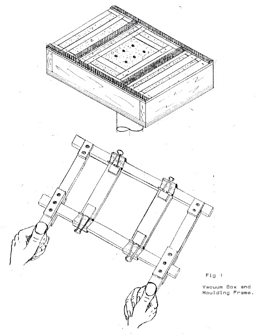
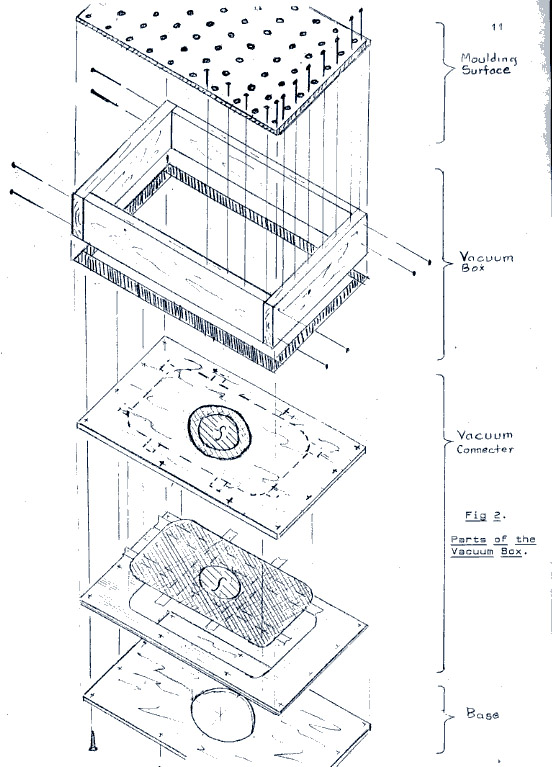
This form of Vacuum Box is comprised of two main components, Fig 1, satisfying two functions: the Vacuum Box proper and the Moulding Frame. The function of the box is to confine, control and direct the vacuum force originating from, in this case, an household vacuum appliance while balancing and broadening its effect over the area of the Moulding Surface. The purpose of the Moulding Frame is to hold the sheet plastic while heating, in the current instance, by inserting the frame and plastic in an oven, and to apply the heated malleable plastic over a mould fixed to the Moulding Surface of the Vacuum Box. The Vacuum Box: as illustrated in Fig 2 is, in turn, composed of four parts: the Moulding Surface, the Box, The Vacuum Connector and the Base.
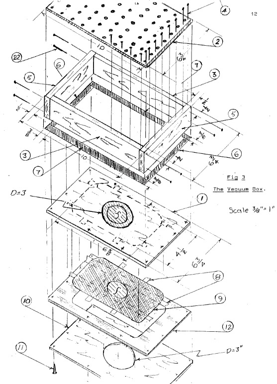
Construction begins with the Box. As diagrammed in Fig 3 a simple four-sided box is built of 1/2 inch hardwood (3,5) of the dimensions given held together with finishing nails (22). This is not necessarily the only size one has to consider but for most canopies in the 1/72 scale range it has proven adaptable and efficient as to the application of vacuum force. A sealer is applied to the underside of the box to render it air-tight. The Sealer (6) is Foam Tape Weather Stripping of the dimensions shown stuck directly to the box by means of its own self-adhesive.
The Moulding Surface or top of the box is built next. It's constructed of 1/8 inch Pegboard with holes spaced 1 inch apart (2). Insure that an edge is left sufficient to allow Vi inch finishing nails (4) to affix the Moulding Surface to the Box as shown.
The Vacuum Connector together with the Moulding Frame are considered the two defining features of this particular Vacuum Box: the Connector because of its efficiency and simplicity in providing an air-tight connection, and the Frame because in addition to being simple to construct is both efficient and adaptable to various sizes of sheet plastic.
The Vacuum Connector consists of three elements: the Interior Base (1) The Airtight Vacuum Connector (9) and the Connector Surround (12). The Interior Base is 1/8 inch plywood with a hole of 3 inch diameter cut into the centre. Woodworkers may have no difficulty drilling the hole, which is to accept the nozzle of the vacuum cleaner, but taking the piece to a commercial craftsman, after explaining its use as best as able, is another solution.
By then cutting off the top of a paper vacuum cleaner bag, in this case an Electrolux type, we have the Airtight Vacuum Connector. The rubberized membrane, which is part of such bags, permits an airtight fit around the vacuum nozzle after it is pressed through the membrane.
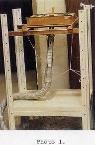
Such an airtight seal is a necessary prerequisite for any vacuum box and this is about as easy as possible. The vacuum nozzle and hose will have to be held in place by means determined by the type of stand available. As illustrated (Photo 1) it was simply tied in position.
It is anticipated that with use the membrane may tear. However, this is again easily rectified as the Connector (9) is secured to the underside of the Interior Base with masking tape which renders it easily replaceable.
The Vacuum Connector is completed with the Connector Surround (12), a 6 ^A x 10 inch piece of cardboard Photo Backing having a space cut out to snugly fit around the Airtight Vacuum Connector (9).
The Vacuum Box is completed by securing the Exterior Base (10) - 1/8 " plywood with 3 inch diameter hole - in place so as to secure the Vacuum Connector to the bottom of the box.
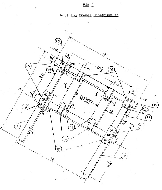
The Moulding Frame: used to hold sheet plastic consists of two Support Arms (13); two Handle Arms made of parts A(14) and B(15) and, two Adjustable Inner Arms (17).
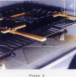
The Support Arms and Handle Arms of the dimensions given were constructed of " Screen Mould but other hardwood may be used instead. Of importance is that the Support Arms extend at least 1 " beyond the Handle Arms as shown. This is to allow the frame to support itself on bricks or other similar non-flammable material in the oven at a height well clear of the lower element while allowing the plastic to "droop" or "sag" the required amount (Photo 2).
HERE GREAT CAUTION AND NORMAL SAFETY MEASURES MUST BE EXERCIZED WITH RESPECT TO FIRE AND INHAILATION, VENTILATION AND USE OF RESPERTORY APPARATUS.
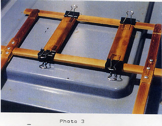
The Handle Arms are attached to the Support Arms by means of Upper Flanges A (16) and B (18) - 1/16 " Hardwood Tongue Depressors - screwed in place, and by Lower Flanges A (20) and B (21) - again Tongue Depressors or other very thin hardwoods glued in place with carpenter's glue. Tongue Depressors or the like are available in craft stores. (Or at the doctor's office provided you are sure you get your own after your exam.) Very thin pieces of wood are necessary so that the Frame with the plastic achieves an airtight fit over the mould on the Moulding Surface. The glue, after hardening, should present no problem for it is only in the heat source, the oven, for a few minutes at a time (Photo 3). However, this too should be carefully monitored.
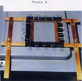
The Adjustable Inner Arms (17) have Flanges (16) attached by glue alone but only on the upper side as indicated. Held in place by removable Binder Clips - 18 one inch clamps with removable handles were used to hold both the plastic and the adjustable arms (Photo 4) - the Adjustable Inner Arms are thus allowed to vary their span within the frame. This is one of this Vacuum Box's distinguishing features: the ability to easily permit a variety of sizes of sheet plastic to be used to accommodate a variety of mould sizes, within limits.
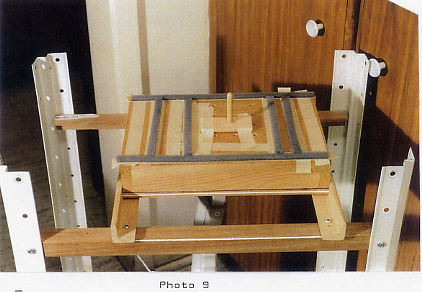
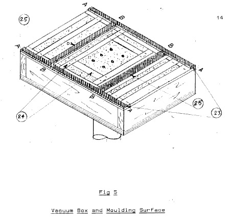
As shown in Fig 4, the Adjustable Inner Arms are set at 4 inches apart and the Moulding Surface is set correspondingly. Fig 5. That is, the moveable Moulding Surface Sealer BB (25) has the same span while masking tape is used to temporarily close off all the surface holes except six that are selected Fig 5 (Photo 9). As it will be observed, the moveable or semi-permanent Moulding Surface Sealer AA and BB are stuck to the masking tape which is in mm stuck to the Moulding Surface. This permits all of the sealers to be removed or changed as required.
Operation
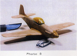
Once the fuselage of your aircraft say, a Mustang, has been carved it would be wonderful and a great time-saver if, as suggested by some, you could just lop off the cockpit portion and use this as your mould. While some modelers proceed this way, I find it not only extremely difficult but also basically impractical.
Impractical firstly because in most instances, both in the interest of realism and to secure the canopy to the body, a small edge of the plastic must overlap the edge of the body where they meet. Therefore, the mould obtained in this fashion will not fulfill these requirements.
Secondly, to compensate for "webbing" - the tendency for a material to "drape" or "tent" over a mould progressively outwards from the top downwards rather than fit snuggly - it is advisable to carve the mould, from the start, so that it consists of an additional or elevating portion lying below the required mould.
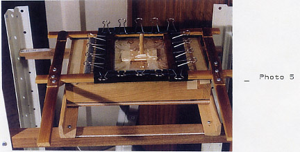
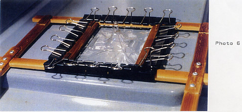
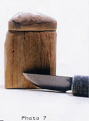
This elevating portion will generally be equal to between one-half and two-thirds of the two portions combined that make up the composite mould. When webbing occurs, which it invariably does, an allowance has already been made beforehand so that the resulting extraneous plastic may simply be cut away. This technique, at its extreme, is illustrated in (Photos 5,6) and (7, 8) where the mould for a turret required a very elongated section in anticipation of webbing.
Ideally, with practice, the extra length to be added to the mould will be easily estimated. Even webbing itself, again with practice and given sufficient vacuum force, may be eliminated. However, the method as described, in the interim, is simple and works.
Carve the mould so as to attempt to err on the smaller side as opposed to the cross-section of the completed fuselage. This will result in a tighter fit which will aid in gluing the plastic to the wood. As well if later an attempt is made to construct a moveable or opening canopy a tight fit will again be required.
Finally, after sanding the mould very smooth and applying wax to assist in later removing the plastic, secure the mould to the Moulding Surface by means of masking tape. The mould also may be raised on coins to permit greater suction around the base.The Plastic:
The sheet plastic used in the present example - ABS (Acrylonitrile Butadien Styrene) - was .008 x 6 x 6 1/2 inches with the Moulding Frame and Moulding Surface set at 4 inches. That is, the span of the Frame was set at 4 inches and the distance between the Sealers BB and BB(25) was also set at 4 inches. The "extra" holes were sealed with removable masking tape as shown (Photo 9).
The plastic may appear to be too thin for our purposes but be mindful that the models were in the 1/72 scale range and that much of the strength of the canopies derives from their shape as is the strength of a cylinder or sphere.Procedure:
The mould is made ready on the Moulding Surface; the plastic sheet is held on to the Frame by means of Binder Clips - the bottom clip-handles of which are later removed before being placed in the heat source, the oven (Photo 4); the vacuum appliance has been attached to the Vacuum Box, secured to its support (Photo 1) and tested, and; the oven supports for the Frame are in place (Photo 2) - situated, as recommended by Walsh, at least 12 inches above the lower element so the plastic will remain clear after "drooping" or "sagging".
In the present case, as illustrated, a drip-pan adequately prohibits the plastic from ever touching the lower element while at the same time acting as the Frame support.
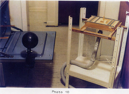
After a lamp is put in place (Photo 10) to enable observation of the "behavior" of the plastic in the oven; leather gloves to shield hands, stop-watch and required safety equipment are made ready we are prepared to enter the realm of art as it pertains to moulding.
Following the method adopted, the oven was set on "broil" (high) and, with the Frame and plastic resting on its support, an unbroken concentrated observation of the plastic begins. After a short period of time, the plastic will be seen to tighten itself within the Frame. At this point, the identification of which is not precise but will depend on experience, the "art" of our project, the stop-watch is set to time the sagging of the plastic that will now commence.
As the plastic heats it will droop. In this case it will be about 2 inches below the Frame. The objective is to allow the plastic to sag sufficiently to present a volume approximating the volume of the mould. This takes about 3-4 minutes and by timing the process a number of spare moulds are easily duplicated.
Just prior to this stage the vacuum is turned on. Now, quickly, remove the Frame from the oven and place it firmly over the awaiting mould (Photo 5).
Remove the Frame with the plastic from the mould (Photo 6). After replacing the lower handles of the Binder Clips to enable their removal, the desired canopy or turret is retrieved.
After the extraneous webbing is cut away, a canopy present itself ready to be masked and glued in place.
This is only one approach among many to build plastic parts. But, as it works, is flexible, inexpensive and relatively easy to construct and operate; it is offered as another alternative to enhance the realism of carved wooden models - the grail of that wonderful, ingenious and enduring hobby, Solid Scale.
To convert to metric it is not necessary to be precise. For example, 25mm allowance for over-lay of the Frame Support Arm should be sufficient to provide stability when the Frame is placed in the oven.
List of Materials
PC Name No Description Size
1 Interior Base 1 1/8" Plywood 6 3/4 x 10
2 Moulding Surface 1 1/8" Pegboard 6 3/4 x 10
3 Vacuum Box Side 2 1/2" Hardwood 1 1/2 x 9
4 Finishing Nails 34 1/2" Finishing Nails
5 Vacuum Box Side 2 1/2" Hardwood 11/2 x 6 ū
6 Base Sealer 2 Foam Tape* 3/16 x 3/8 x 6 3/4
7 Base Sealer 2 Foam Tape* 3/16 x 3/8 x 10
8 Masking Tape 3/4" Masking Tape
9 Airtight Vac Connector 1 Top Only of Vacuum Bag 41/2x65/8
10 Exterior Base 1 1/8" Plywood 6 3/4 x 10
11 Screws 12 Round Head Wood Screws #6 x 5/8
12 Connector Surround 1 Photo Backing 6 3/4 x 10 of
same thickness as 9. 13 Frame Support Arm 2 1/4" Screen Mould 1/4 x 3/4 x 14
14 Frame Handle Arm A 2 1/4" Screen Mould 1/4x3/4 x51/4
15 Frame Handle Arm B 2 1/4" Screen Mould 1/4 x 3/4 x 61/4
16 Flange Upper A 6 Tongue Depressors 1/16 x 3/4 x 1 ―
17 Adjustable Inner Arm 2 3/16 Hardwood 11/4 x 5 1/4
18 Flange Upper B 2 Tongue Depressors 1/16 x 3/4 x 3
19 Screws 10 Round Head Wood Screws #6x1/4
20 Flange Lower A 2 Tongue Depressors 1/16 x 3/4 x 1 ―
21 Flange Lower B 2 Tongue Depressors 1/16 x 3/4 x 3
22 Finishing Nails 8 3/4" Finishing Nails
23 Moulding Surface 2 Foam Tape * 3/16 x 3/8 x 10
24 Masking Tape 3/4" Masking Tape
25 Moulding Surface 2 Foam Tape * 3/16 x 3/8 x 6
Foam Tape* = Foam Tape Weather Sealer Stripping: Self-adhesive
Bibliography
Jackson, H. D. Building Model Airplanes from Scratch. Blue Ridge Summit, PA: Tab Books, 1979.
Lenches Jr, William J. "Making an inexpensive Vacuum Forming Machine," Fine Scale Modeler, March 1998, 76-79.
Percival, Pat. "Cross Hobby's Vac-Former," Flying Models 106, December, 2001,72-74.
Walsh, Douglas E. Guide to Vacuum Forming for the Hobbyist. Lake Orion, Ml: Vacuum Form, 1998.