Turing Tumble is P-Complete
(Draft Proof Sketch)
H. James Hoover
Version 0.4 - 2019-03-07
Version 0.5 - 2019-05-26 Version 0.6 - 2025-01-10
Marble Machines
Scott Aaronson in The Power of the Digi-Comp II [1] has a very nice result that shows that the Digi-Comp II abstract machine is equivalent to Comparator Circuits [2]. Scott's abstraction, which he calls a Pebble Machine (PM) consists of a reservoir of balls, a collection of flip-flop elements connected by channels into a directed acyclic network, and a lever at the exit from the network at the bottom that releases the next ball from the reservoir.
Released in 2018, Turing Tumble [3] by Paul Boswell is the most recent incarnation of a marble computer. The Turing Tumble Machine (TTM) abstract machine is an Aaronson PM extended with these two features:
-
An additional ball reservoir plus release leaver is added. The reservoirs are called Blue and Red. As a ball exits the computation network it can trigger either the Blue lever or the Red lever to release a ball from the corresponding reservoir.
-
Using gears, 2 or more flip-flops can be coupled so that a change in state of any 1 flip-flop causes the coupled flip flops to change to the same state. Thus a coupled flip-flop still only has 2 states, but introduces new, correlated, paths.
It is feature (2) that will enable us to construct a ball duplicator, which give us the ability to do fan-out, which will enable a reduction of the Monotone Circuit Value Problem (MCVP) to the Turing Tumble Value Problem (TTVP), and thus show that TTVP is P-Complete.
Note that in our reduction, feature (1) is just a convenience, and can be eliminated. See Appendix below.
The Turing Tumble Value Problem (TTVP) is defined as follows: Given a circuit of flip-flops, an initial configuration of all the flip-flops, b balls in the Blue reservoir, and r in the Red, compute the final configuration of all the flip-flops.
As Scott points out, there are all kinds of equivalent variant definitions of the value problem for circuits. I like this one because I'm interested in the intermediate states of the computation, where the flip-flops store the previous state resulting from processing the inputs so far.
Related Results
Matthew Johnson [4] has a nice P-Complete result that uses a variant of NorCVP (i.e. all gates are NOR gates). He also shows that when an exponential number of marbles are available, then TTVP is P-Space complete.
Animation
Before proceeding, it is worth watching an animation of our construction. It was created with the Turing Tumble Simulator by Jesse Crossen. Two Duplicators In Action
Construction and Behaviour
The key to the MCVP reduction is being able to handle fan-out. We do this by constructing a ball-duplicator (DUP), below left. Two instances of it are in the sample circuit on the right.

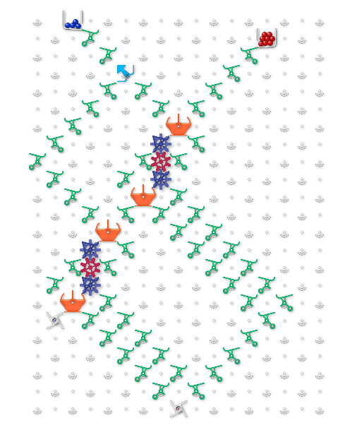
It has 2 inputs Signal in (SIGin) and Trigger in (TRIGin); and 3 outputs Signal out (SIGout), Trigger out (TRIGout), and Duplicate out (DUPout). The duplicator has two states Pass - pass through, Dup - duplicate. The diagram shows the duplicator in the Pass state. The orange blocks are simply cross-over gates, and don't add any intrinsic power to the TTM except to allow the circuit to be planar.
In the Pass state, a ball on TRIGin routes to TRIGout, while a ball on SIGin sets the duplicator to Dup state and routes to SIGout. In the Dup state, a ball on TRIGin resets the duplicator to Pass state and routes to DUPout where it can then enter into more computations. A ball is never supposed to enter on SIGin when the duplicator is in the Dup state.
Note how the computation proceeds in phases. Each phase has two parts a blue computation, and a sequence of red computations.
The phase begins with the release of a blue input ball. As the ball passes through the circuit it encounters simple flip-flops to perform the usual PM operations (the blue flip-flop at the top left of the board in the animation).
The ball can also take the SIGin -> SIGout path at a duplicator, which puts the duplicator into the Dup state. When the ball reaches the bottom of the circuit it hits the red lever, and this releases a red ball into the TRIGin of the topmost duplicator. The computation is now in the red part of the phase.
All of the duplicators are connected into a path where the TRIGout of the one above connects to the TRIGin of the one below, and the TRIGout of the last duplicator connects to the blue lever.
As the red ball follows the trigger path, when it encounters a duplicator in the Pass state, it leaves via TRIGout into the next duplicator. But when it encounters a duplicator in the Dup state, the ball is routed via DUPout into the part of the circuit that "computes", this achieving a fan-out of 2 for the original ball that set the duplicator. The ball exiting the compute part of the circuit will release another red ball.
In the animation, observe how the 2 blue balls are duplicated into 4 computation paths.
If there are f duplicators in the circuit, then potentially 1+f red balls need to be fed through the duplicator trigger path in order to ensure that all the duplicates are processed from the previous input, plus one final ball to confirm that no duplications remain. Once all the duplications are complete, the ball exits the final TRIGout and releases the next blue input ball, thus starting the next phase.
One potential concern is connecting the chain of duplicators. Note that during a duplicate cycle, when a gate in the MCVP circuit triggers a duplicate, no DUP gate for an upstream logic gate will subsequently trigger, so f+1 steps in the duplicate phase is sufficient. This means that the chain of DUP gates can be ordered arbitrarily, not say in topological order, and this makes the uniformity condition easier, as the DUP gates can just be numbered on-demand as the logic gates are being processed.
Complexity
Let the MCVP instance have n inputs, size s, depth d, with f of the gates with fanout 2. (Note f <= s)
Then the TTVP instance will have n blue balls, n * (1 + f) red balls, s+n simple flip-flops (n for the input distributer), and f duplicators. The depth will be max(d, f).
Thus evaluating the TTVP instance is in P (function P actually).
The circuit transformation should be possible with any of the various members of the P-completeness family of reducibilities.
References
[1] Scott Aaronson. The Power of the Digi-Comp II: My First Conscious Paperlet, 2014-07 (approx), https://www.scottaaronson.com/blog/?p=1902
[2] Cook, Filmus, and Lê. The Complexity of the Comparator Circuit Value Problem, ACM Transactions on Computation Theory, Vol. 6, No. 4, Article 15, Publication date: August 2014.
[3] Turing Tumble https://www.turingtumble.com/
[4] Matthew P. Johnson. Turing Tumble Is P(SPACE)-Complete, Algorithms and Complexity, 11th International Conference, CIAC 2019, Rome, Italy, May 27-29, 2019, Proceedings, pp.274-285.
Appendix
-
Input Distributer
A tree of flip-flops will distribute input balls to each of the leaves of the tree, thus processing each "bit" of input per phase. The routing of the leaf to a 0-rail or 1-rail determines the value of the bit.
-
Single Ball Reservoir
The Red reservoir can be elminated. Because there are always f+1 steps in the duplicate part of a phase, an additional distribution tree could be placed at the top. The first leaf of the tree routes a ball into the blue input distributor. The remaining leaves route all the f+1 balls into the red trigger path. The tree is of size 2^k where k is the smallest such that 2 + f <= 2^k If 2 + f is not a power of of 2, then there will be some superfluous balls in the trigger step, but no more than f. Here is an example of the same circuit as above, recast to use only one ball reservoir, complete with an animation Single Reservoir In Action

-
Prototype Duplicator Running on Actual Turing Tumble
-
Flip-Flops as Logic Gates
Balls represent signal pulses. So you need a 0-rail and a 1-rail, where the presence of a ball on the x-rail represents logical value x.
Monotone gates are designed so that exactly 1 ball leaves the gate to perform a computation. For OR, the first ball to arrive leaves as the gate output, and the second ball if any is routed to the discard path down to the bottom of the circuit. For AND, the first ball to arrive is routed to the discard path, and the second ball if any leaves.
-
Double-Rail Logic
Each signal to a gate is represented as two rails, with these properties: -
rail-1 iff ! rail-0
i.e. when a gate value is finally computed, a ball is on one rail or the other, not both. -
no ball appears on an output rail until the gate value is determined.
-
AND gate
-
out-1 = x-rail-1 ^ y-rail-1
-
out-0 = x_rail-0 v y-rail-0
-
OR gate
-
out-1 = x-rail-1 v y-rail-1
-
out-0 = x_rail-0 ^ y-rail-0
Revision Log -
Version 0.4 - 2019-03-07 - initial version.
-
Version 0.5 - 2019-05-26 - added link to Matthew Johnson's result.
-
Version 0.6 - 2025-01-10 - cleaned up paragraph just before Complexity section.