3.3.9 Fluid control systems
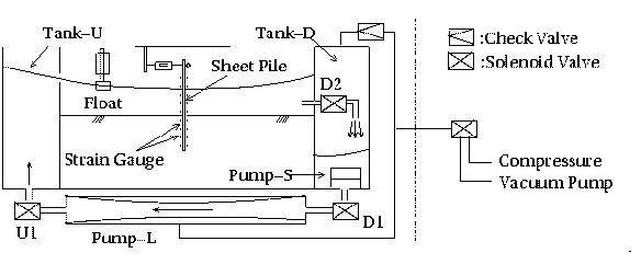
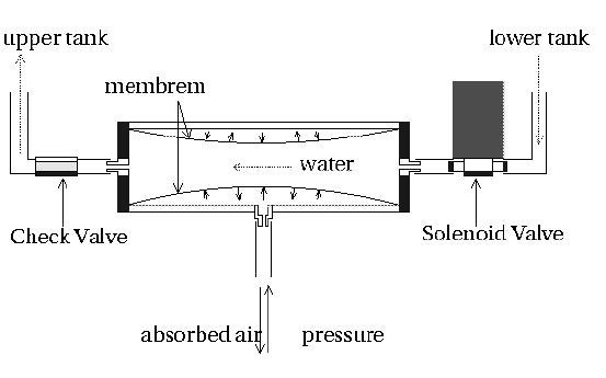
An example of the use of fluid control system is shown in Fig. 3. A water circular that cloud be mounted on a soil container was developed to maintain water tables in both upstream and downstream sides of the sheet pile. The water supply is used to maintain the upstream water table constant during the flight. After a centrifuge acceleration is reached at the intended level, the solenoid valves SV is opened. Then the water table in the downstream of the sheet pile is drawn down to the level of the outlet and kept constant. The elevation of the outlet is variable. If seepage occurs and the water table in the upstream of the sheet pile is lowered, the float switch in Fig. 4 is turned on, and the water circular feeds the water in Tank-D and Tank-U. Once the water table in the upstream of the sheet pile recovers to the prescribed elevation again, the float switch is turned off, then the water circular is disabled. A differential head DH is thus kept constant during a centrifuge model test.
Reference
Ueno, K., Yokoyama, Y. and Murata, M. (1998) : Using image processing in centrifuge research, Proc. of CENTRIFUGE 98 (in print).
|
|
|
|