UART(Universal Asynchronous Receiver & Transmitter) [1] |
This part of the application notes introduce the digital UART and its usage.
What is a UART? |
The UART (universal asynchronous receiver and transmitter) module provides asynchronous serial communication with external devices such as modems and other computers [2]. The UART can be used to control the process of breaking parallel data from the PC down into serial data that can be transmitted and vice versa for receiving data. The UART allows the devices to communicate without the need to be synchronized.
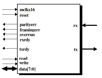
The UART consists of one receiver module and one transmitter module. Those two modules have separate inputs and outputs for most of their control lines, the lines that are shared by both modules are the bi-directional data bus, master clock (mclkx16) and reset. The UART high level schematic is shown in Figure 1 below.

When do we need a UART? |
1) Control the receiving and transmitting time of the data:
Since the data stream has no clock, data recovery depends on the transmitting device and the receiving device operating at close to the same bit rate. The UART receiver is responsible for the synchronization of the serial data stream and the recovery of data characters.
2) Increase the accuracy and decrease the effect of the noise:
The UART system can tolerate a moderate amount of system noise without losing any information.
Implementation of a digital UART by VHDL |
VHDL can be used for the behavioral level design implementation of a digital UART and it offers several advantages.
The advantages of using VHDL to implement UART:
- VHDL allows us to describe the function of the transmitter in a more behavioral manner, rather than focus on its actual implementation at the gate level.
- VHDL makes the design implementation easier to read and understand, they also provide the ability to easily describe dependencies between various processes that usually occur in such complex event-driven systems.
- It is easier to test the UART by the VHDL simulation and find out if any discrepancy occurs.
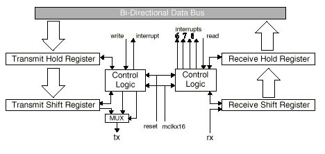
The UART block diagram is shown in Figure 2 below.

How do we use the UART? |
The use of the UART can be confusing at first but is rather straightforward once an understanding of the UART is acquired.
To begin, let us take a look at the UART data format. This implementation of the UART transmits in blocks of 11 bits; 1 leading low start bit, 1 trailing high stop bit, 1 parity bit and 8 data bits. The UART data format is shown below.

The transmit and receive line of the UART are held high while no transmission/reception is taking place. In the transmission of a sequence the active low start bit indicates to the receiving UART that a new sequence of data is on its way. This causes the receiving UART to take the next 8 bits as the transmitted data and the bit after that as the parity of these 8 data-bits. Lastly, a high stop bit is used to indicate the end of a block. The parity can be set as even or odd and is used to indicate whether or not there has been an error in the received data bits. Note that errors can still occur even if the parity bit indicates no parity errors. For example, if the transmitted sequence is "11110000" and the parity is set as even, the parity bit that would be transmitted with the sequence would be '0'. If the received sequence is "11101000", the calculated parity of this sequence also equals the transmitted parity bit of '0', thereby fooling the receiving UART into thinking that there were no errors in transmission.
Note: The data is transmitted LSB first. Therefore, if "10101010" is the data to be transmitted, the transmitted/received data appears as "01010101". The whole sequence would therefore be transmitted/received in this order: "00101010101" for even parity, and "00101010110" for odd parity.
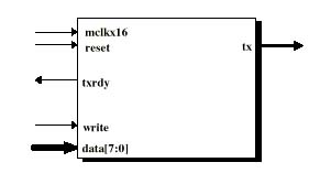
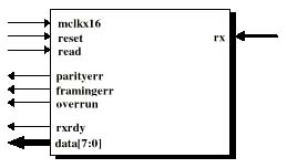
The UART module is composed of 2 modules; the transmitter and the receiver as indicated in Figures 4 and 5 below. The operation of these two modules is not discussed here (with the exception of the baud rate clock generator) as it is not required to be able to use the UART module. For further information concerning this, refer to the UART App note or the respective VHDL code.
The top-level schematic of the transmit and receive module
are shown in Figures 4 & 5 below.
 |
 |
|
|
|
In order to use the UART you need to know what baud rate you want to transmit at. The transmitter and receiver modules have been designed with a clock divider inside, which runs 16 times slower than the clock signal sent to it. Therefore, there should be a clock divider running at 16 times the baud rate driving the UART modules.
If for example, you want to transmit at 33.6 kbps and the FPGA board runs at 25.175 MHz then:
Baud rate x 16 = 33600 x 16 = 537600
Clock division ratio = 25175000 / 537600 = 46
Clock divisor = 46 / 2 = 23
Therefore, the clock divider used to clock the UART would have
a divisor of 23. This would give a transmission rate of about
34.2 kbps.
The implemented UART module has 12 I/O ports, which are used to control it, get I/O to and from it, and to determine it’s status.

| Symbol | Type | Description |
| mclkx16 | Input | Master input clock for internal baud rate generation |
| reset | Input | Master reset |
| parityerr | output | Indicates whether a parity error was detected during the receiving of a data frame |
| framingerr | output | Indicates if the serial data format sent to the rx input did not match the proper UART data format |
| overrun | output | Indicates whether new data sent in is overwriting the previous data received that has not been read out yet. |
| rxrdy | output | Indicates new data has been received and is ready to be read out. |
| txrdy | output | Indicates new data has been written to the transmitter |
| read | Input | Active low strobe signal, used for reading data out from the receiver. |
| write | Input | Active low strobe signal, used for writing data in to transmitter. |
| data (7 down to 0) | In/Out | Bi-directional data bus for sending/receiving data across the UART |
| tx | Output | Transmitter serial output. Held high when no transmission occurring and when resetting |
| rx | Input | Receiver serial input. Pulled-up when no transmissions taking place. |
The process of transmitting data through the UART begins by first checking the txrdy line. A high txrdy signal indicates that new data can be written to the transmitter. To write to the transmitter place the data to be transmitted on the data line. The data is then latched into the UART's transmit module by a leading low signal to the write line. This is all that is required to transmit the data since the UART will take care of the rest. The next data sequence can be latched once the txrdy line goes high again. Note that while not transmitting, the data line must not be driven but left floating (i.e. set to "ZZZZZZZZ") in order to avoid logic contention. This requires the use of tri-state buffers and is not discussed here. One way to avoid dealing with this is to modify the UART module by giving it separate parallel input and output ports.
The process of receiving data through the UART begins by waiting for the rxrdy line to go high. A high rxrdy indicates that data has been received and is ready to be read out. To read the data out from the UART's data line assert a low signal to the read line. This will latch the received data from the receiver to the data line allowing you to read it. The parityerr, framingerr, and overrun lines indicate any problems with the current received data. The process of handling these errors will not be discussed here. Apart from this that is basically all that is required to receive data through the UART. The next data received can be read out once rxrdy goes high again.
For a better overall understanding of what has been discussed you can refer to sample waveforms of the transmit, receive and uart modules (Press shift while clicking). These waveforms require the use of Altera's MAX+Plus 2 software in order to view. MAX+Plus 2 v9.23 was used to compile these waveforms.
From the above discussion of the UART and it’s I/O signals, the usage of the UART should be straightforward.
Note:
- there are no FIFO buffers for this UART implementation.
- the UART related VHDL files on this page have been modified from the original versions.
- total number of logic cells used for the UART module = 78
If you want more...
Download the following vhdl files, which incorporates a transmit FIFO and a receive FIFO with the UART. This file strictly only handles the transmission and reception of data. Hence, it does not check if the FIFOs are full or not or whether any errors occured in the transmission/reception of data.
uart_ctrl.vhd, uart_ctrl_pkg, fifo.vhd [3], rxcver.vhd [1], txmit.vhd [1]
To use this controller just compile the package then the uart_ctrl.vhd file. The 2 input ports write_data and read_data are used for telling the controller when the data to be transmitted is ready and when to read out the received data, respectively. The data_in port is for the data that is to be transmitted and the data_out port is for the data that has been received to be read out. The reset is active high and the clock should be at 16 times the desired baud rate as mentioned above.
Note that the 2 FIFOs were made using Altera's MegaWizard Plug-in Manager [3] and take up 486 logic cells.
References |
[1] QuickLogic Application Notes and QuickNotes
http://www.quicklogic.com/support/anqn/an20.pdf (Original UART App Note from QuickLogic) or here an20.pdf
http://www.quicklogic.com/support/anqn/uart.exe (Original UART VHDL and Verilog files from QuickLogic) or here uart.exe
[2] Motorola MCore: MMC2001 Reference Manual, Motorola, 1998
[3] MegaWizard Plug-in Manager, Altera MAX+Plus II v9.23, 1999