Linear Feedback Shift Register
Abstract
A Linear Feedback Shift Register is a sequential shift register with combinational logic that causes it to pseudo-randomly cycle through a sequence of binary values. Linear feedback shift registers have multiple uses in digital systems design.
Applications Include:
A design modeled after LFSRs often has both speed and area advantages over a functionally equivialent design that does not use LFSRs.
An explanation of how to use LFSRs for these applications can be found in the sales primer for a Linear Feedback Shift Register Megafunction sold by Altera. This is a PDF file.
Theory of Operation
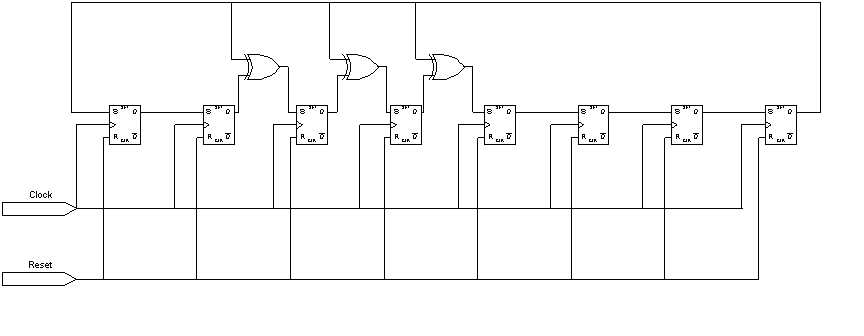
Feedback around an LFSR's shift register comes from a selection of points (taps) in the register chain and constitutes XORing these taps to provide tap(s) back into the register. Register bits that do not need an input tap, operate as a standard shift register. It is this feedback that causes the register to loop through repetitive sequences of pseudo-random value. The choice of taps determines how many values there are in a given sequence before the sequence repeats. The implemented LFSR uses a one-to-many structure, rather than a many-to-one structure, since this structure always has the shortest clock-to-clock delay path.
A diagram of an eight bit LFSR is as follows:

8-Bit LFSR
Optimum Tap Points
The choice of which taps to use determines how many values are included in a sequence of pseudo-random values before the sequence is repeated. Certain tap settings yield the maximal length sequences of (2N-1).
The following table shows a minimum number of taps that yield maximal length sequences for LFSRs ranging from 2 to 32 bits.
|
Number of Bits |
Length of Loop |
Taps |
|
2 |
3 |
0,1 |
|
3 |
7 |
0,2 |
|
4 |
15 |
0,3 |
|
5 |
31 |
1,4 |
|
6 |
63 |
0,5 |
|
7 |
127 |
0,6 |
|
8 |
255 |
1,2,3,7 |
|
9 |
511 |
3,8 |
|
10 |
1023 |
2,9 |
|
11 |
2047 |
1,10 |
|
12 |
4095 |
0,3,5,11 |
|
13 |
8191 |
0,2,3,12 |
|
14 |
16383 |
0,2,4,13 |
|
15 |
32767 |
0,14 |
|
16 |
65535 |
1,2,4,15 |
|
17 |
131071 |
2,16 |
|
18 |
262143 |
6,17 |
|
19 |
524287 |
0,1,4,18 |
|
20 |
1048575 |
2,19 |
|
21 |
2097151 |
1,20 |
|
22 |
4194303 |
0,21 |
|
23 |
8388607 |
4,22 |
|
24 |
16777215 |
0,2,3,23 |
|
25 |
33554431 |
2,24 |
|
26 |
67108863 |
0,1,5,25 |
|
27 |
134217727 |
0,1,4,26 |
|
28 |
268435455 |
2,27 |
|
29 |
536870911 |
1,28 |
|
30 |
1073741823 |
0.3,5,29 |
|
31 |
2147483647 |
2,30 |
|
32 |
4294967295 |
1,5,6,31 |
Optimum Tap Points for Maximal Length Sequences
VHDL Code Usage - LFSR_Generic.vhd
The implemented LFSR is coded for maximal length (2N-1), where N is the number of bits in the LFSR. The VHDL entity can be instantiated with an LFSR bit width of 2 to 32.
The parallel "seed" input port (same length as the bit width) can be used to start the LFSR sequence at a certain position in the pseudo-random sequence. Assertion of the Active High "Load" signal at the rising edge of a clock will load the seed value into the LFSR.
Before the LFSR is used for the first time, the Active Low "Reset" must first be asserted to initialize the Taps lookup table. One should ensure that "Load" and "Reset" are not asserted at the same time or else undetermined behavior will result.
The LFSR outputs pseudo-random sequences in both serial and parallel format for extra flexibility.
The VHDL code for the LFSR as well as a component instantiation example are provided.
VHDL Testing
Our group has tested this code in MAX+plus II. If you attempt to use this code and it does not work, please email Raymond Sung
Authors: Raymond Sung, Andrew Sung, Patrick Chan, Jason Mah