by Raymond Sung, Andrew Sung, Patrick Chan, Jason Mah
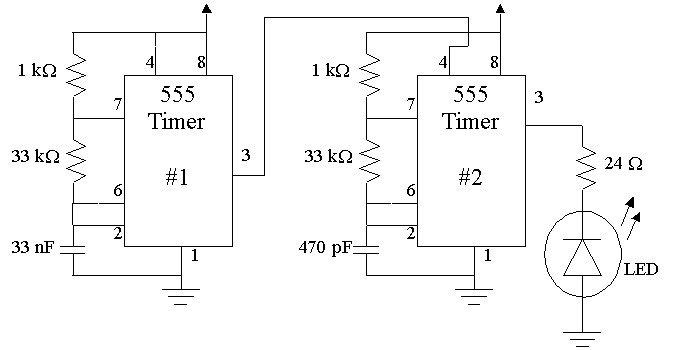
A circuit diagram for an infrared (IR) transmitter
was found on-line, designed by Mr. Ryan White. This design calls for an
IR LED, two 555-timers and a collection of resistors and capacitors. This
design modulates the IR transmitter at 45 kHz, to trigger the decoder located
on the IR receiver circuit. This carrier signal will modulate within a
square-wave
envelope of 600 Hz. This is to enable the GP1U52X
(Radio Shack Receiver) since it scans for an incoming signal, modulating
between 100 and 1000 Hz

Both timers are set up for a 50% duty cycle. The following
analysis begins with the second 555-timer, configured as an a-stable oscillator.
NOTE: when the capacitor is charging,
Vss = Vcc and the timing equation is used to find
the charge time of the capacitor; which in-turn equals the length of one
pulse.
T1 = tl ln [ (Vss - VI)/(Vss - Vf) ]
T1 = (Ra + Rb) C { ln [ (Vcc - VI)/(Vcc - Vf) ] } Ra = 1kW Rb = 33kW C = 470pF
T1 = (1kW + 33kW ) (470pF) { ln ( [ (Vcc - 1/3Vcc)/(Vcc - 2/3Vcc) ] }
T1 = (1kW + 33kW ) (470pF) ln 2
T1 = 1.1 x 10⁻⁵ sec
For the discharging capacitor, assume Vss = Vce sat = 0.2 V to complete our analysis. The timing equation is then used to calculate the discharge time.
T2 = t2 ln [ (Vss - VI)/(Vss - Vf) ]
T2 = Rb*C { ln [ (Vcc - VI)/(Vcc - Vf) ] }
T2 = 33kW (470pF) {ln ( [ (0.2 - 10/3)/(Vcc - 5/3) ] }
T2 = 1.2 x 10⁻⁵
sec
Since T1 @
T2 the duty cycle is very close to 50%, where the error in T1 and T2 is
within acceptable limits for proper operation. This 45 kHz. oscillating
pulse will appear on pin 3 of the 555-timer and should look like the waveform
below:
The first 555-timer pulse overlays the second 555-timer pulse - creating an envelope for the carrier signal. Again using the timing equation, the envelope frequency is calculated.
T1 = tl ln [ (Vss - VI)/(Vss - Vf) ]
T1 = (Ra + Rb) C {ln [ (Vcc - VI)/(Vcc - Vf) ] } Ra = 1kW Rb = 33kW C = 33nF
T1 = (1kW + 33kW ) (33nF) {ln ( [(Vcc - 1/3Vcc)/(Vcc - 2/3Vcc) ] }
T1 = (1kW + 33kW ) (33nF) ln 2
T1 = 7.8 x 10⁻⁴ sec
T2 = t2 ln [ (Vss - VI)/(Vss - Vf) ]
T2 = Rb*C {ln [ (Vcc - VI)/(Vcc - Vf) ] }
T2 = 33kW (33nF) {ln ( [ (0.2 - 10/3)/(Vcc - 5/3) ] }
T2 = 8.3 x 10⁻⁴ sec
This creates the following waveform:
The final output to the IR LED
will now resemble:
To make the transmitter portable,
a 5-volt regulator is connected to a 9-volt battery. Lastly, a 24 W
resistor is placed in series with the IR LED, to limit the current and
control the voltage. Using this small resistor gives increased output and
dramatically increases the range of transmitter. However, the batteries
drain much faster.
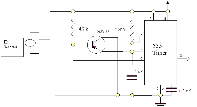
Mr. Ryan White also designed
this circuit. The GP1U52X IR detector obtained from RadioShack, first demodulates
the incoming signal and then checks to see if the modulated frequency is
within range. This is accomplished as the 555-timer recharges a capacitor
through a resistor. If indeed the capacitor recharges, then the incoming
signal is too slow, meaning that the IR received is not the signal emitted
by our IR transmitter.
