THE SIMULATOR
Once you have created your VHDL file and it successfully compiles, you are ready to simulate. First, a file must be created containing the waveforms you wish to test. This file has the extension .scf
Creating a new simulation file:
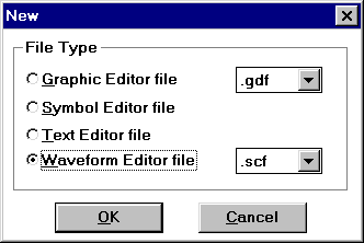
Choose File->New… or click on the button on the left side of the toolbar that looks like a blank page. This window should show up:

figure 6.1
Choose Waveform Editor file and make sure the extension is .scf. Then click OK. A new waveform window will appear.
Entering signal names:
To enter the signals you want to view on the waveform, go to the menu bar and click on Node->Enter nodes from SNF…. A window will appear so you can choose which nodes you want:
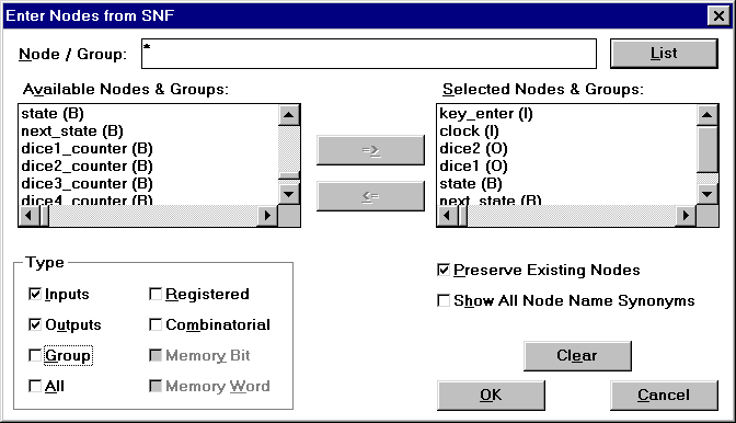
figure 6.2
Click on the List button for a list of the available nodes for your current project. The list shows up in the Available Nodes & Groups box and you can highlight the ones you want and click on the arrow pointing to the right (the Selected Nodes & Groups box). The letters in parenthesis tell you what type of node you are looking at. The (I) stands for Input, the (O) stands for Output, and the (B) stands for Buried (a signal named within your architecture). Uncheck the Group option unless you want all of your selected nodes to be grouped together.
When you are done selecting the nodes, click the OK button. Your specified nodes should now be displayed on the waveform.
Editing the waveform:
The first thing you want to edit on the waveform is end time. To do this, click on
File->End time… A box will appear where you can enter the end time:
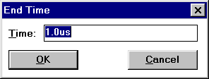
figure 6.3
You can enter a time as ns (nano-), us (micro-), ms (mili-), or s.
You can also set the grid spacing on the waveform. Click on Options->Grid size… and choose an appropriate time interval for the grid spacing. Keep in mind that if you have an extremely small grid size (like 10ns) with a very large end time (like 1s), it could crash the program. This was tested several times.
Once you have set your end time and grid size, you are ready to tell the waveform what input you want it to test. There are several ways to assign values to an input.
If you would like an input to hold the same value for the entire time, click on the input name and click the appropriate value you want it to hold (eg. 1, 0, Z, etc).
![]()
figure 6.4
If you want to clock in input, click on the input name and choose the button with an alarm clock inside it (see above toolbar). The following window will appear:
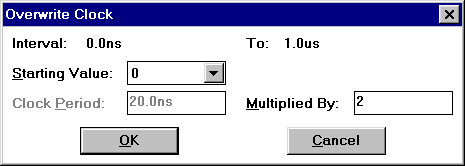
figure 6.5
The Clock Period box cannot be changed, so you must use the Multiplied By box to make the period of your choice. For example, here we are wanting a 40ns clock period (since the Altera boards use a 25MHz clock), so we tell it to multiply the clock period by 2. Clock OK and you will see a waveform of the specified period.
If you want a pattern that is not clocked, you can highlight a section of the waveform and tell it to be 1 or 0 (or any of the other choices on the button bar above). If you hold down your mouse button and move it off of the visible screen, the screen will scroll in that direction as needed.
When you are done editing the inputs on the waveform, you should choose
File->Save as… and save your work. The name of the .scf file should be the same name as your .vhd file (eg., here we are using dice.vhd, so we save as dice.scf). You are now ready to simulate. The following window is an example of what you can do with the above directions:
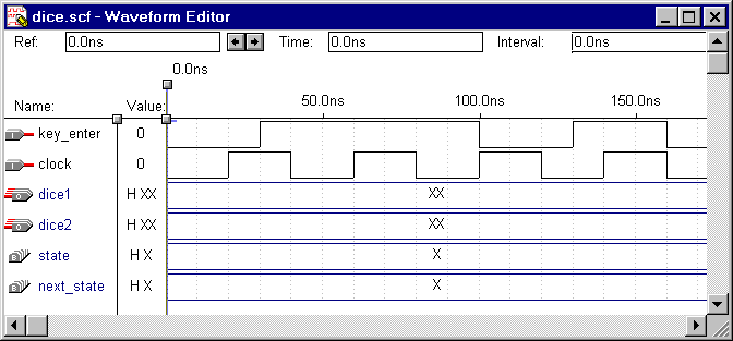
figure 6.6
Note that key_enter was given values by highlighting sections of the waveform and assigning them to 0 or 1. The clock input was done using the clock directions with a period of 40ns. Our grid spacing is 10ns.
Running the simulation:
Click on MAX+plus II->Simulator or choose the simulator button on the toolbar. The simulator window will appear:
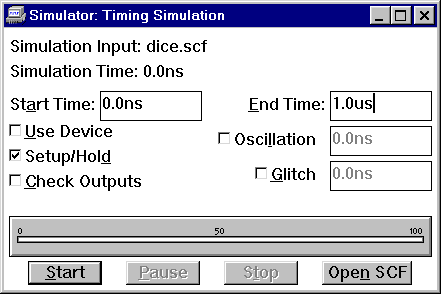
figure 6.7
The Check Outputs box can be checked if you have put into the .scf file what outputs you should have. This will produce what really happens and compare it to what the values should have been. Press the Start button to begin the simulation. It will automatically use the .scf file for the current project.
If any errors or warnings occur during the simulation, a message box will appear for those. To look at the output waveforms for the simulation, click on the Open SCF button. The waveform window will open with your specified input and the resulting output shown. If you included outputs yourself, they will be shown on the same waveform overlapping each other. The following window shows an example that does not use the output checking features:
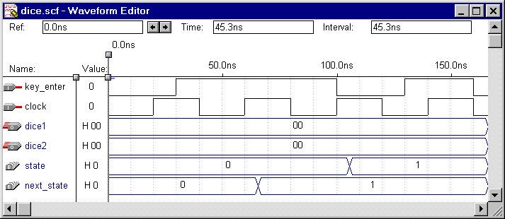
figure 6.8
Note that the states do not have names as they do in Mentor Graphics. You can only have state names if you create a waveform (.wdf) yourself, using state machine (MACH) as the type of signal. The .scf file cannot use state names. Instead, numbers are assigned for each state. In the above example, when next_state is 1, state changes to 1 on the following rising edge of the clock. The next state would be 2, then 3, etc.
Vera Casteel, Mark Fedorak, Kris Pucci, Ron Smith - 1998