AVR Programming via TinyUSB adapter and WINAVR/AVRDUDE
By: Christopher Chmilar Partners: Rajan Jassal, Eric Smith Group 2
What you need:
Atmel AVR 28-pin microcontroller. For the purposes of these notes, the ATMega328P microcontroller is used.
Pocket AVR Programmer. The programmer comes with a 10-pin and 6-pin target ribbon cable.
USB to MiniUSB cable.
Standard breadboard, as well as basic breadboard electrical components (jumper wires, resistors, LED’s).
5.0 V DC Power Supply (Optional).
Windows Environment PC (Windows 7 was used)
This tutorial will go through the steps to properly wire and power the AVR microcontroller to the Pocket Programmer. This tutorial requires the use of the Windows environment to program through the WINAVR/AVRDUDE environment.
About the AVR microcontroller
The ATMega328P contains 28 pins, which is split into 4 groups: 1 group of voltage sources, and 3 groups of I/O pins. There are 3 “clusters” of input/output pins, labeled PB(0-7), PC(0-6) and PD(0-7). Alongside acting as I/O pins - which is assigned during programming - all pins also contain alternative purposes and features. Please refer to the AVR datasheet in associating these pins with their alternative purposes. For these configuration notes, the PB group of pins will be used for their second purpose as in-system-programmer (ISP) pins, the PC group will be used as I/O (except for the Reset pin, PC6), and the PD group will be ignored.
Steps:
Wiring the AVR microcontroller to the breadboard
To program the AVR, a 5.0 V DC power supply must be used as VCC. The AVR contains 4 voltage source pins, 2 of which must be set to a rail providing 5.0 V DC, and 2 to a rail to ground. Wire these ATMega328P pins to the following mandatory sources:
|
AVR Pins: |
Pinned to: |
|
7, 20 |
VCC |
|
8, 22 |
Ground |
Pin 1 (PC6) will be set as the reset input of the microcontroller. Direct this pin to a button switch, with which an input will be tied to the VCC rail, and output will be tied to ground (See picture 1). One of the I/O pins will also be used as a way of determining if programming has been successful. This will be through the use of an LED.This programmed demonstration will use Pin 23 (PC0). Attach a resistor between an output pin and the LED, and direct the LED to a ground rail.
Picture 1) Pin configuration of the AVR. Pin 1 is located at the top right of the AVR, and a reset button is attached. Button has a 10K resistor from VCC rail to top-left of switch, and a jumper from ground to top right of switch. A 3.3k resistor is lead from pin 23 (PC0) to the left-most green LED. This LED is directed to ground.
2. Wiring the TinyUSB 10-pin ribbon to the AVR
The AVR device will be programmed through the use of the in-system-programmer (ISP) protocol. A group of pins at the AVR will be attached to the 10-pin target ribbon via jumper wires . 9 of the 10 pins from the ribbon cable must be wired correctly. The following table details each of the TinyUSB pins, and where they need to be wired:
10-Pin Ribbon Pin Number (Purpose): | Pinned to: |
1 (MOSI) | 17 (PB3/MOSI) |
2 (VCC) | VCC |
3 (Not Used) | |
4 (Ground Wire) | Ground |
5 (Reset) | 1 (PC6/RESET) |
6 (Ground Wire) | Ground |
7 (SCK) | 19 (PB5/SCK) |
8 (Ground Wire) | Ground |
9 (MISO) | 18 (PB4/MISO) |
10 (Ground Wire) | Ground |
Picture 2) 10-pin ISP Ribbon to microcontroller. Note that all top pins on ribbon are even, and all bottom pins are odd. Pins numbers of the AVR jumped to the ribbons are 17.18.19 (ISP) and 1 (Reset).
3. Attaching the AVR Pocket Programmer
Note: Before attaching the ribbon and USB cable to the AVR Pocket Programmer, locate the power switch on the board. If the switch is set to “Power Target”, the Programmer will power the AVR with 5.0 V DC. If the switch is set to “No Power”, the Programmer will not power the board to 5.0 V, but it will however still leak a low amount of voltage. When using AVR microcontrollers named with moniker “P”, such as the ATMega328P, it refers to a processor which can work within low voltage conditions. If you do not have any other voltage source attached to the breadboard, the Pocket programmer will allow the AVR to properly run with the switch set to “No Power”.
After selecting which power setting you would like the Pocket Programmer to perform, attach the ribbon to the 10-port ISP on the board. Connect the MicroUSB cable to the programmer, and connect the USB to a Windows PC.
4. Installing the AVR Pocket Programmer Driver and WINAVR
After plugging the Pocket Programmer to your computer, Windows will attempt to automatically install the proper driver. If the driver fails to automatically install, please refer to the Pocket AVR Programmer Hookup Guide to manually install the driver required.
Once the driver is working, download and install WINAVR. WINAVR will will install the AVRDUDE flash command, the AVR-GCC compiler program, and the Programmers Notepad application. Programmer’s Notepad will be used to design a C file, as well as a Makefile. The Notepad will make and run both files via AVR-GCC to form a HEX file. The HEX file will be flash-programmed using AVRDUDE, which will be flashed through the ISP pins previously wired. The microcontroller then runs the HEX code once it is reset.
5. Creating a C file
Open Programmer’s Notepad from the Start menu.
Create a new file called “LED_ON.c”. Put this file in a folder to be used in testing.
Insert the following into the blank file, and save:
/* LED_ON.c
This code is adapted from “Blink_1MHz.c” Created by
Nathan Seidle of Spark Fun Electronics (2007).
This demonstration code is used to show how I/O pins
Are set, and how the internal clock of the AVR is used.
*/
#include <avr/io.h>
//Definition functions
void ioinit(void); //This will initialize the IO pins
void delay_ms(uint16_t x); //This will provide a millisecond clock
//======================
int main (void)
{
ioinit(); //Set up IO pins
//The LED will be turned on and off at 1 second intervals, based on the
// internal clock of the AVR microcontroller:
while(1)
{
PORTC = 0xFF;
PORTB = 0xFF;
PORTD = 0xFF;
delay_ms(1000);
PORTC = 0x00;
PORTB = 0x00;
PORTD = 0x00;
delay_ms(1000);
}
return(0);
}
void ioinit (void)
{
//DDR(B,C,D) is the data-direction register for the AVR.
//When a bit is set to “1”, that pin is set to output.
//When a bit is set to “0”, that pin is set to input.
DDRB = 0b11111111; //Set all PB Port Pins to output
DDRC = 0b11111111; //Set all PC Port pins to output
DDRD = 0b11111111; //Set all PD Port pins to output
}
void delay_ms(uint16_t x)
{
uint8_t y, z;
for ( ; x > 0 ; x--){
for ( y = 0 ; y < 90 ; y++){
for ( z = 0 ; z < 6 ; z++){
asm volatile ("nop");
}
}
}
}
6. AVRDUDE, and creating a MakeFile
AVRDUDE is a command line tool, used to flash HEX code from the PC to the AVR. It contains only a few arguments that are mandatory to pass. To check the initial device hookup, and ensure the programmer will work properly, open a command window (Start menu, type “cmd” and hit Enter) and type in the following:
avrdude -c usbtiny -p atmega328p
The “-c” argument passes along which form of communication the PC has to use to program the AVR. In this case, the format is the AVR Pocket Programer, which uses the usbtiny standard. The “-p” command passes which AVR microcontroller is being initialized. If you are not using the ATMega328P, please follow this list of AVRDUDE options to find the command to program the micro of your choice. The following command window shows the correct initialization output if the test is successful:
Instead of constantly writing into the command-line, a “Makefile Template” will be used to automatically make and program the C code written in Programmer’s Notepad. Create a blank file called “Makefile”(case-sensitive) in the same folder as LED_ON.c. Copy and paste the following template to the Makefile, and save. This template is public domain, and quite robust in configuration settings. A number of settings will need to be changed in the Makefile:
MCU = attiny13 changed to MCU = atmega328p (or whichever micro code is being used)
TARGET = softpwm_t13 changed to TARGET = LED_ON
AVRDUDE_PROGRAMMER = avrispmkII changed to AVRDUDE_PROGRAMMER = usbtiny
Save the Makefile. The AVR is now ready to be programmed:
In the Programmer’s Notepad, Select Tools -> [WinAVR]Make Clean.
Select Tools -> [WinAVR]Make All
Select Tools -> [WinAVR]Program
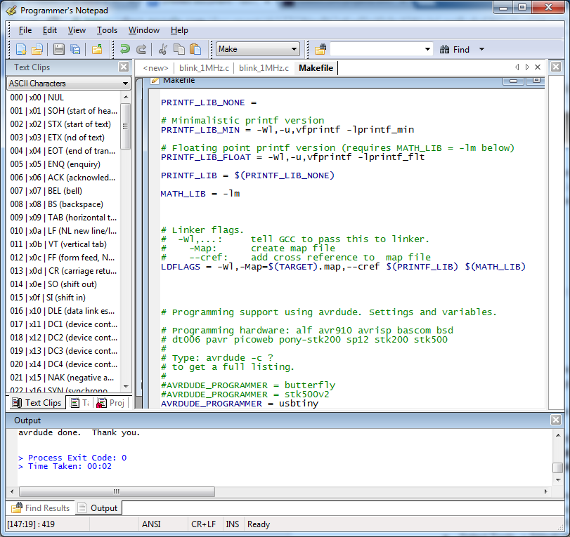
The Output pane at the bottom on the program will display the AVRDUDE command outputs while performing makes and programming. This information displayed will detail the flash process of the created HEX code onto the AVR. The following should display if programming is successful:
The LED attached to the AVR at pin 23 should now be periodically blinking on and off every second. The configuration is properly working. To expand on programming the AVR via C and the Programmer’s Notepad, please refer to your AVR microcontroller’s respective datasheet to further expand on programming the AVR through C (registers, flags, interrupts and internal clock fusing).
LINKS:
Pocket AVR Programmer Hookup Guide
Authored by: Christopher Chmilar
Partners: Rajan Jassal, Eric Smith