This is both app notes for how to get the Virtex 2 Pros in the lab working with EDK version 10.2 and also a quick start guide to how to get all the code/VHDL for failsafe module project working.
Relevant Files:
FilesStart a new project with the following device properties:
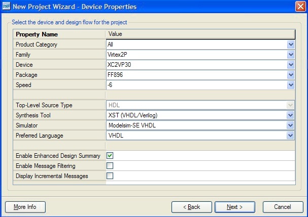
Note: Not critical if you don't use modelsim, though it is the better behavioural simulator
Create a new source, choose Embedded Processor (entitled system in this example):
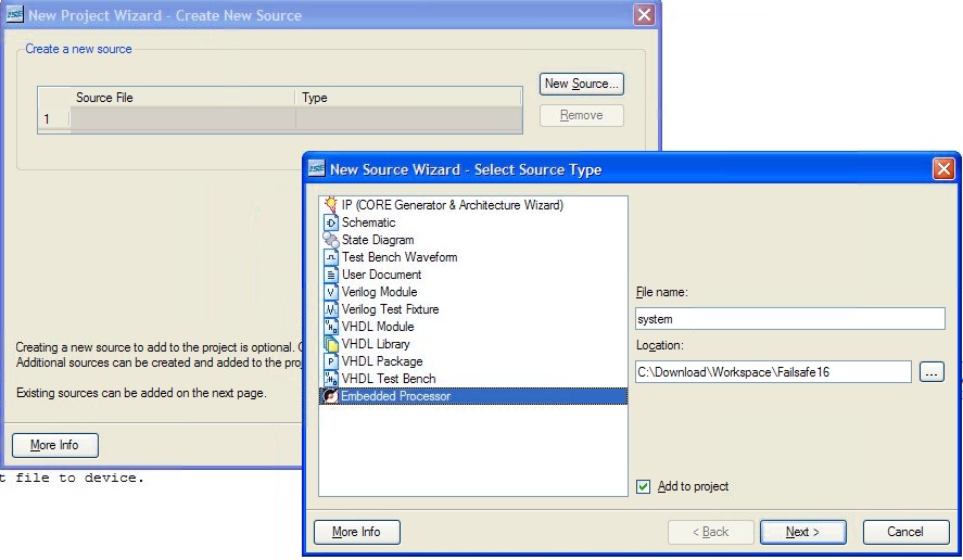
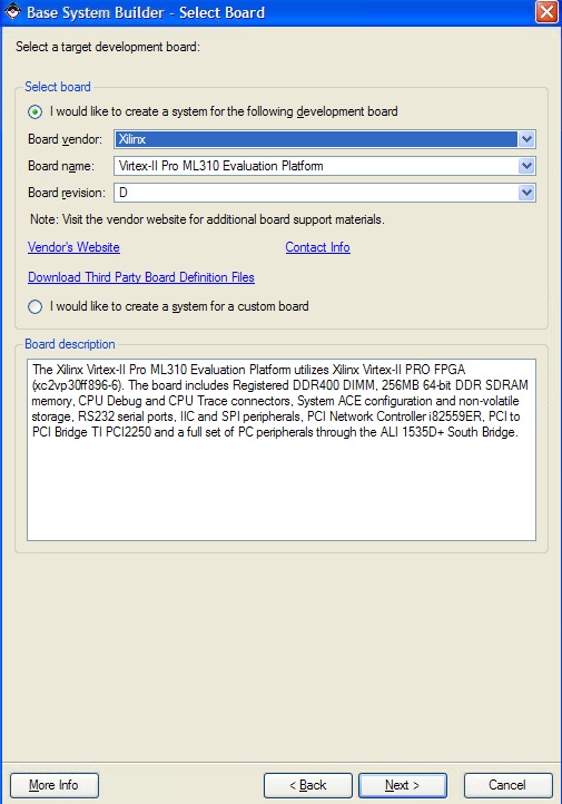
Everything else you can leave default and keep clicking next until you finish. EDK will then automatically start up. Answer yes whe it asks you to build a Base System using the BSB builder. Create a new Design. Choose the following system:
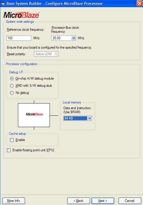
Choose MicroBlaze as your Processor:
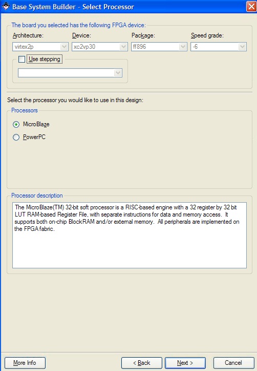
Select the processor-bus clock frequency at 25mhz (or make sure your synthesis will work with whatever frequency you choose, or set up constraints ). Use at least 16kb of BRAM (or else it's likely the memory map in sdk will fail depending on what libraries you link/how big you code is). 64kb is used here. You can enable cache and FPU if you actually need the performance.
Select the UART as your only IO device if you want to receive debugger input/output from serial(leaving this out in the example). An XPS timer is also added as a peripheral (failsafe code requires a timer).
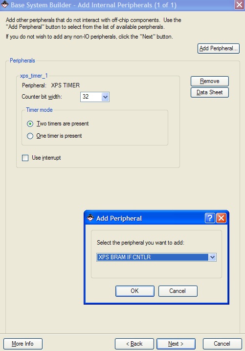
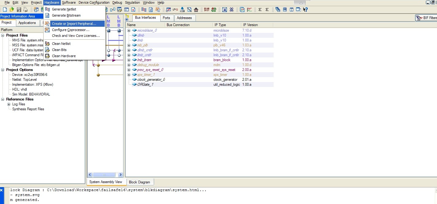
Use defaults for everything else and generate. Now we need to add our own custom peripherals. In this example we'll be using the custom peripherals we designed for our failsafe module. To do this we'll have to create a peripheral than re-import it. Click hardware->create or import peripheral
Use defaults for everything else and generate. Now we need to add our own custom peripherals. In this example we'll be using the custom peripherals we designed for our failsafe module. To do this we'll have to create a peripheral than re-import it. Click hardware->create or import peripheral
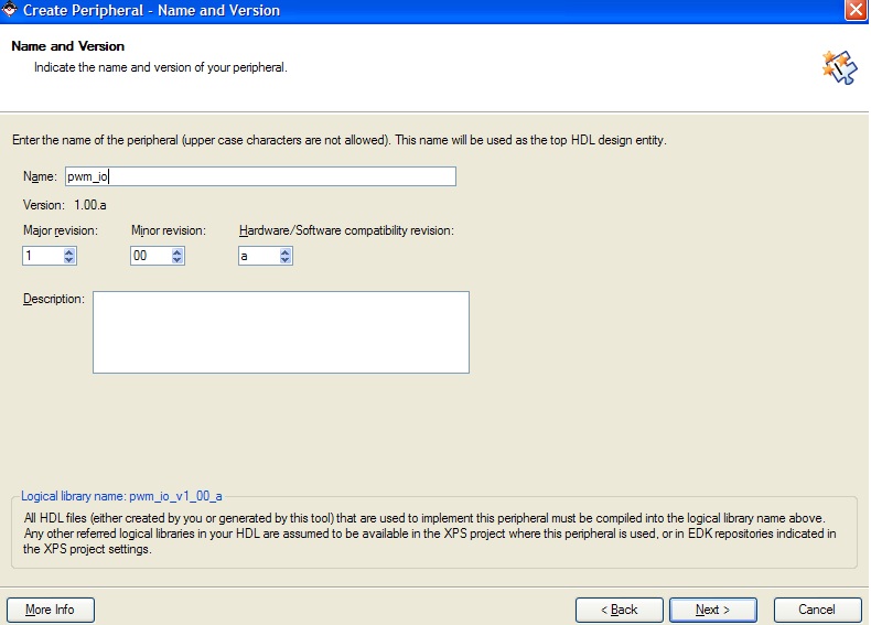
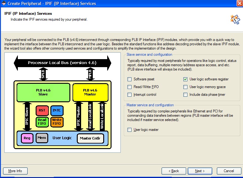
Accept defaults until it asks you for the name of your peripheral. In this case we use the pwm_io as the name of our peripheral.
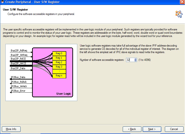
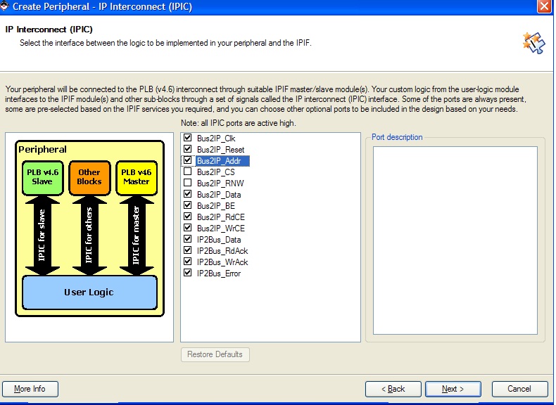
Don't include Data Phase timer in IPIF services, select 32 software accessible registers, and select Bus2IP_Addr in the IPIC menu. (these particularities are needed for the VHDL peripheral code that is supplied). For everything else, just accept defaults.
Keep hitting next until finish. Some notes: Generating BFM simulation is useful for simulating if your custom peripheral is working as intended given the correct bus signals. However you need to get xilinx to ask IBM for a license to do it. I managed to get the license (just a sign up on the xilinx websites) to do this and the BFM simulation (mostly) working but the whole procedure
was messy so I won't include it for now. Generating ISE and XST project files lets you open/edit your custom peripheral from ISE editor. By default Xilinx creates user logic stubs for you (the default is just memory mapped
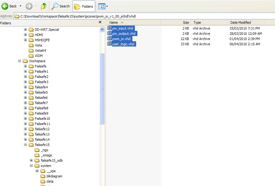
registers which you can read/write to). Your custom peripheral vhdl files are kept in
In this example we provide these files for you under the VHDL directory. Copy and overwrite user_logic.vhdl, pwm_io.vhdl, pw_input.vhdl and pw_output.vhdl into the pcores\pwm_io_v1_00_a\hdl\vhdl directory:
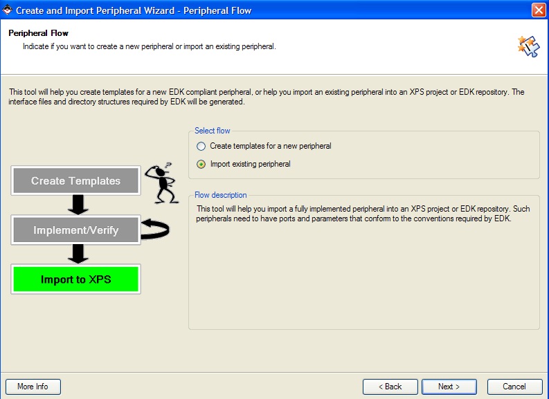
We now have to import the peripheral again into the project. Click hardware->create or import peripheral again. This time click import existing peripheral:
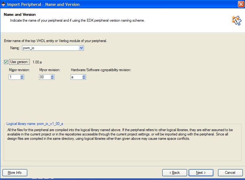
Under Name and Versio use pwm_io and version 1.00a and click yes when it asks you to overwrite.
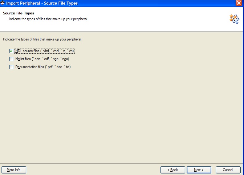
click HDL source files in the Source File Types menu:
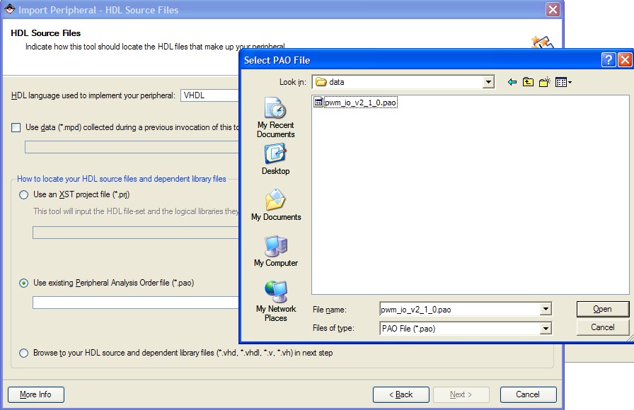
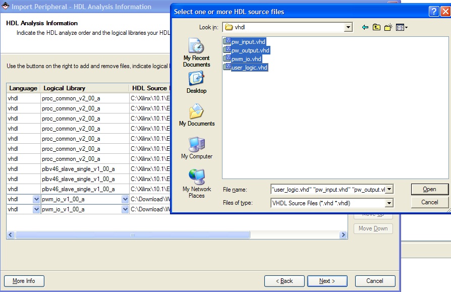
Use existing Peripheral Analaysis Order file in the next menu and select the file:
In the next menu add all the files you copied into the pcores\pwm_io_v1_00_a\hdl\vhdl (user_logic.vhdl, pwm_io.vhdl, pw_input.vhdl and pw_output.vhdl) directory.
Select PLBV46 Slave (SPLB) as the bus interface in the next menu. Keep clicking next until you reach the "Identify interrupt signal" page. de-select "Select and configure interrupts" (We won't need this for this project). Then click next until you hit finish. The pwm_io peripheral is properly created for the project.
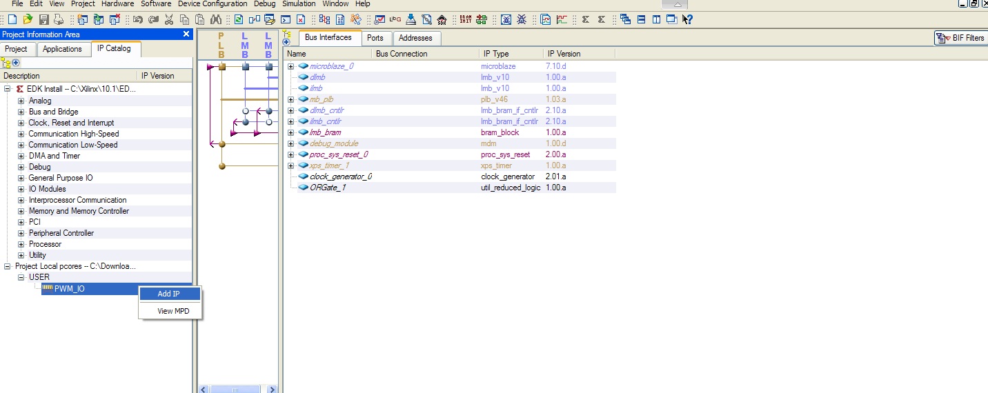
Add the pwm_io peripheral by clicking on IP catalogi, selecting Project Local pcores-> User->PWM_IO and choosing add IP
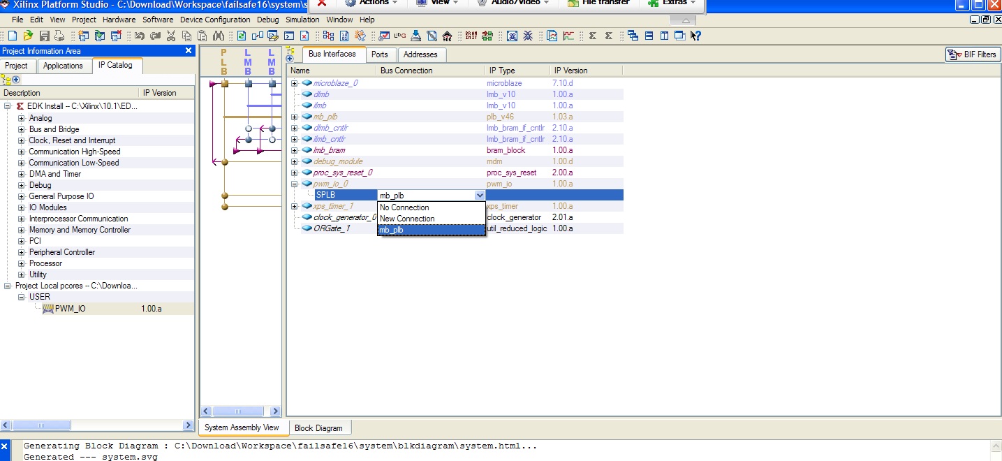
Choose mb_plb as it's bus connection
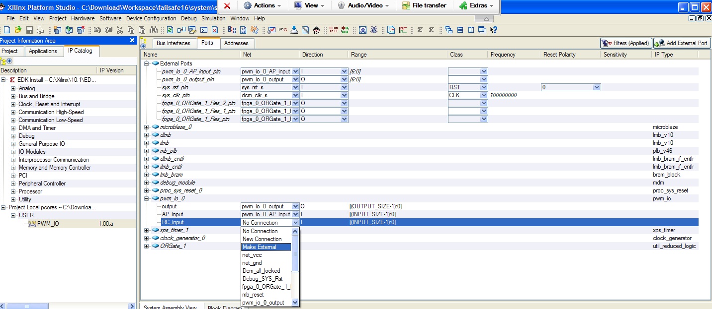
in Ports choose Make External for all pwm_io_0 ports (output, AP_input, RC_input). This sets up the ports as input/output pins on the board.
in Adresses, click generate addresses to generate the address for the pwm_io peripheral.
Next we modify the system.ucf file. Note that the system.ucf file the edk generates is not correct. Specifically the sys_clk_pin and sys_rst_pin are chosen incorrectly. Setting them AJ15 and G25 works fine. Also input/output pins will probably need to be need to be set to 3.3V by using IOSTANDARD = PCI33_3 in order for the design to be implemented. The system.mhs file indicates which ports need to be mapped. Modify the system.ucf file to your needs or use the one provided:
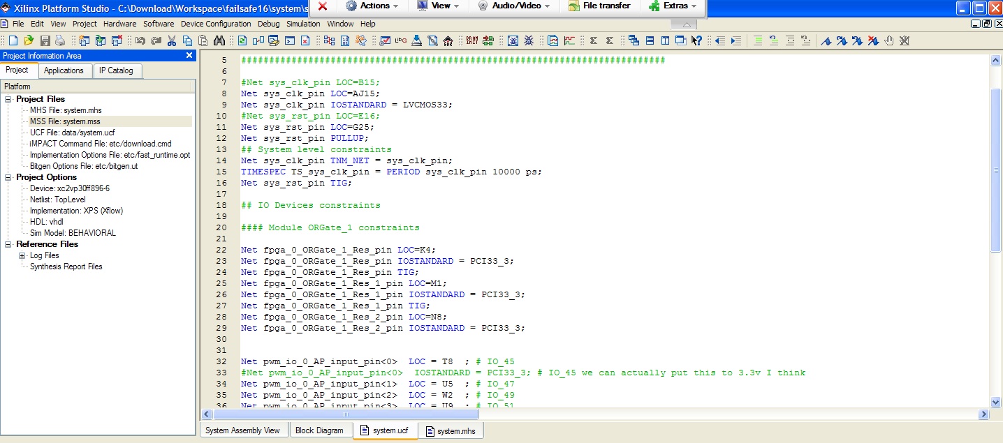
We can now synthesize the design. Add the system.ucf (in
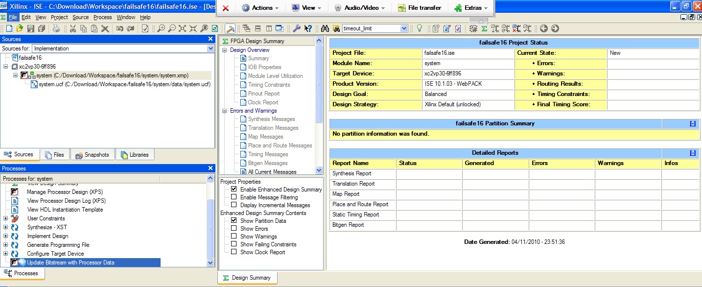
We're now ready to work with the SDK. For this example copy the source files provided.
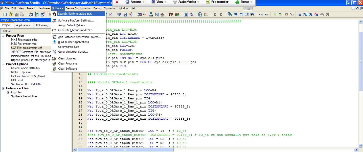
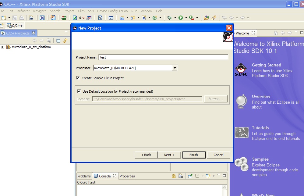
Launch the SDK, create a new project,test, (use defaults) and copy over the source files from the "C Code" folder to
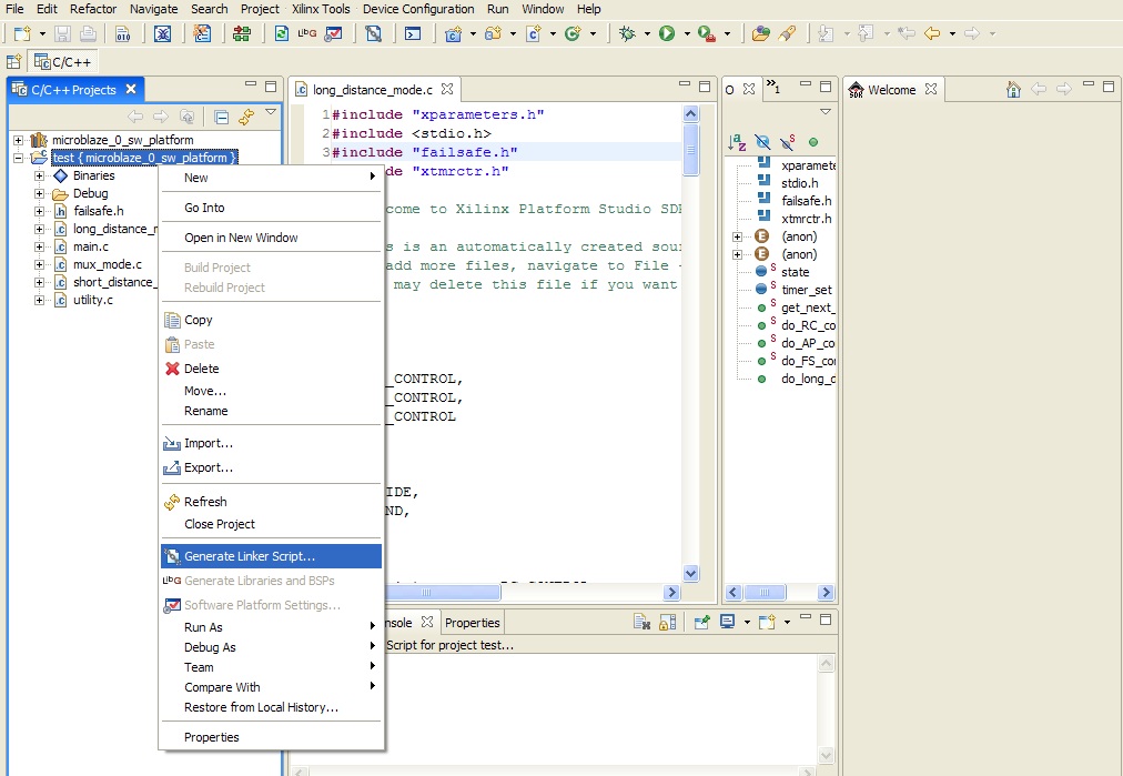
Right click the project and select generate linker script. (You'll also have to do this everytime you make hardware changes).
Do Device configuration-> Program FPGA to program the FPGA with your hardware (you'll have to do this everytime you modify hardware) and right-click your project and click debug/run to debug/run your project.
Do not be tempted to use a 64 bit operating system when using ISE 10.1 as Xilinx does not officially support it. While the installation and the Project Navigator will probably all work, you still need the 64 bit cable drivers to program the Virtex 2 pros. While there is a version of 64 bit impact that you can use to program the device with the Project Navigator, whatever the SDK is using will still use 32 bit version of Impact. Long story short, it is strongly recommended you stick to windows XP 32 bit. Also note that support for the Virtex 2 pros were dropped after Xilinx 10.1 so you have no choice but to use Xilinx 10.1 if you want to use the Virtex 2s.
If you're using the usb cable to program the FPGA you'll have to modify the impact script so that it chooses the right device. Edit the
Make sure you use the "volatile" (look this up on google if you don't know what it does) keyword when accessing memory-mapped registers.
As mentioned before the EDK will not generate constraints for custom peripheral so either create these constraints yourself or be sure that your design meets the bus clock frequency (check the synthesis)
I have often encountered the "bug" that when you attempt to run/debug a program you encounter a "Microblaze is under reset" message. There were to independent reasons I encountered for this. The first being that the custom peripheral didn't meet the bus clock frequency. And the second reason being because the constraint file (auto-generated by the edk) was not correct. Both solutions to this are mentioned in the app notes.