This tutorial explains how to control the infrared emitter (LTE 4208) and receiver (R3208E), which we received from the lab stock, using the DE0 Nano board. This procedure can also be adapted for the DE2 board.
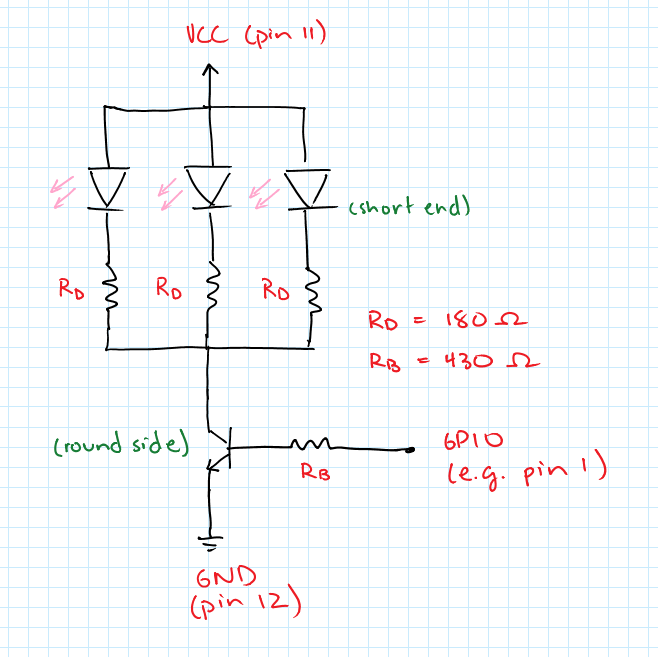
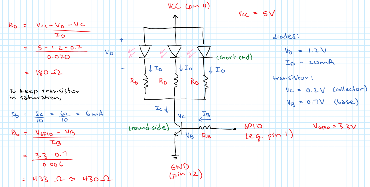
- Power diodes using GPIO power pins at 5 V.
- Each emitter diode has maximum current I_D=20 mA.
- Each emitter diode has voltage drop V_D=1.2 V.
- Limit current through diodes with resistor R_D, with value chosen so that the current does not exceed 20 mA.
- Turn diodes on and off using 2N4401 transistor (in stock) connected to GPIO output pin at 3.3 V.
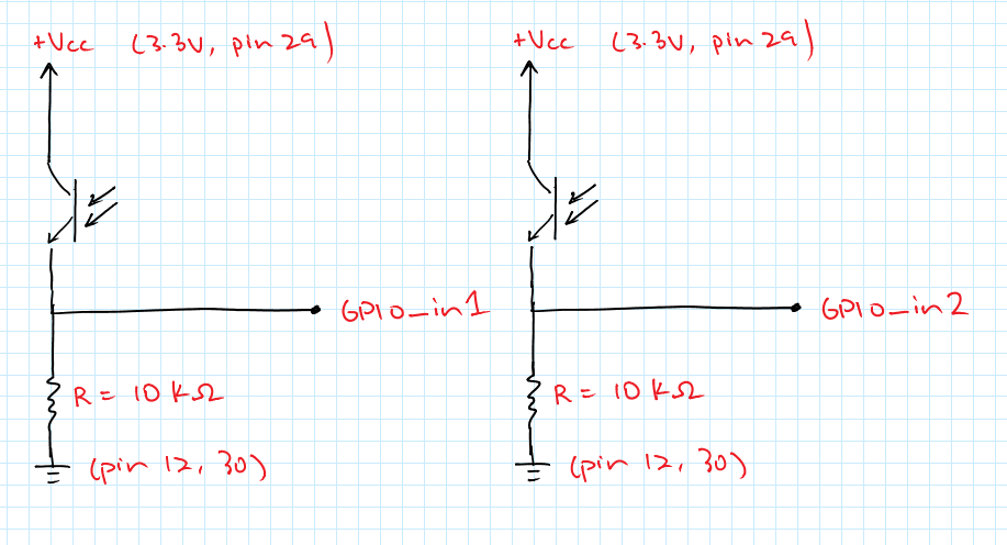
- Each receiver is a phototransistor that turns on as it receives infrared light.
- GPIO input pins pulled up towards 3.3 V when infrared light received, pulled down to ground through 10 "kΩ" pull-down resistor when no infrared light received.
Download the Quartus archive file de0_nano_system.qar. Once you've downloaded it:
- Double-click the archive file to open it up in Quartus.
- Quartus will bring up a dialog box to Restore Archived Project. The default destination folder will be {location of archive file}/de0_nano_system_restored. Rename it to /InfraredDemo and click OK.
- Compile the design. You'll have warnings but there should be no errors.
- Program your DE0 Nano.
- Go to InfraredDemo/Appnote/README.txt for instructions on how to set up the software.