Terasic Technologies has provied an I2C library on the DE0-Nano Demonstration CD to use for the Altera Development boards. The 2 required library files for I2C are:
I2C protocol uses 2 wires to comunicate. A clock line (SCL) and a data line (SDA). For more information, refer to I2C on Wikipedia
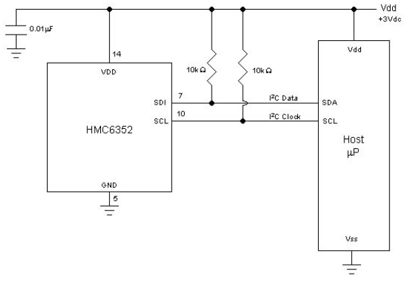
Pull Up Resistors: Most I2C devices require pull up resistors for both the clock and data lines. Simply place a resistor between SCL and VDD, and another between SDA and VDD. Devices that run on 3.0V generally requires 10k resistors. The following image is taken from the datasheet for our Compass Module - HMC6352 to demonstrate the pull up resistors:
Start Sequence: Initial start sequence at the beginning of every command. To indicate a start sequence, the SDA line goes low while the SCL line is held high. This tells the I2C device a command is starting.
Stop Sequence: The stop sequence is defined when the SDA line goes from low to high while the SCL line is held high.
Address Sequence: The device selection sequence is a total of 9 bits long as follows:
| Address | Read/Write | ACK |
|---|---|---|
| 7 bits | 1 bit | 1 bit |
Data Sequence: The data sequence is also 9 bits long, but with a minor change:
| Data | ACK |
|---|---|
| 8 bits | 1 bit |
bidir_port_to_and_from_the_i2c_sda => GPIO_0(7)Write: The board will communicate to the device by sending 8 bits of data. The first seven bits are used to represent the device address and the folling bit is used to indicate whether it is a read or write command (0 = write, 1 = read). For example using the HMC6352, the write address is 0x42 and the read address is 0x43. After sending the address sequence an ACK signal should be received. After the address command is sent it is followed by the the desired control or data sequence.
To do a write command from c code, call the folling function. This function includes all needed sequences such as the start and stop sequences.
bool I2C_Write(alt_u32 clk_base, alt_u32 data_base, alt_8 DeviceAddr, alt_u8 ControlAddr, alt_u8 ControlData);
Where clk_base is the base address of the i2c_scl PIO component,
and data_base is the base address of the i2c_sda PIO component,
and DeviceAddr is the device address,
and ControlAddr is the sub address (if applicable),
and ControlData is the data or command you are wanting.
For example: I2C_Write(I2C_SCL_BASE, I2C_SDA_BASE, 0x42, 0x00, 'W');
Read: Most devices require sending a command first to select which data you want to read. In the included library files, reading first writes a command to the device to select the data, then sends the 'address + 1' sequence to represent the reading address, and then it reads in the returned data.
bool I2C_Read(alt_u32 clk_base, alt_u32 data_base, alt_8 DeviceAddr, alt_u8 ControlAddr, alt_u8 *pControlData);
Where clk_base is the base address of the i2c_scl PIO component,
and data_base is the base address of the i2c_sda PIO component,
and DeviceAddr is the device address (the function automatically accounts for the read/write bit),
and ControlAddr is the sub address (if applicable),
and pControlData is a pointer to where to store the read data.
For example: alt_u8 data[5];
I2C_Read(I2C_SCL_BASE, I2C_SDA_BASE, 0x42, 0x00, data[0]);
SCL Frequency: Can be modified by changeing the value in the following statement in I2C.c
#define SCL_DELAY usleep(1)
Default is 1. If you increase the delay, the clock frequency will slowed down correspondingly. If you have trouble reading signals, first try reducing the frequency incase the device requires a slower clock.