Created by: Jordan Tymburski and Rachita Bhatia of Group 4.
When: In 2012 During CMPE 450/490
References: Terasic and a Toronto DE2 Video Project
The ADV 7181B chip is part of the Altera DE2 board that provided the ability for decoding tv analog input. However, the format that comes from the chip is still decoded in a serial format known as ITU-R 656. So, to get it working, the chip needed to be initialized using an I2C interface and then the video was decoded into usable format with pixel data that included the coordinate location on the screen.
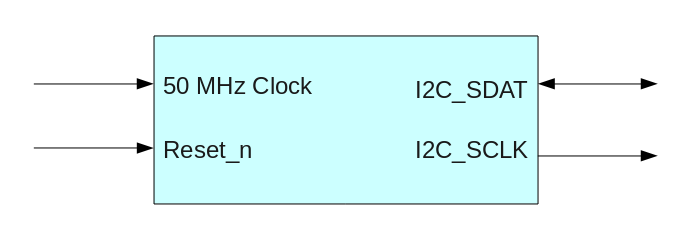
The first part is the I2C interface, which I only needed to make a small bug modification from the version that Terasic provided. The version that Terasic provided was available on our lab computers in the '/opt/altera' directory. The module has the following structure:
The code can be downloaded here in zipped format.
References: Terasic (/opt/altera) - couldn't find a link online
The second part is the actual video decoding process. This was a heavily modified version from one done in Toronto University. The original version that we started with didn't work at all with the DE2 board we were working with. However, the module that they designed for decoding the ITU-R 656 standard was mostly correct and only needed a couple of changes to clean up some special cases. The finalized version had the following structure:
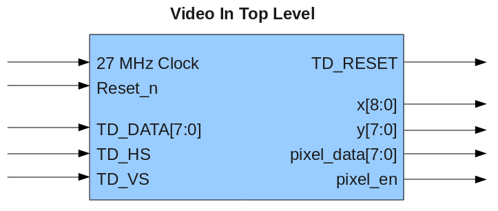
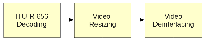
The outputted data is a frame that is sized to 320 x 240 by removing the odd frame part of the ITU-R 656 standard and removing every other x pixel to cut the resoluton in half. The resulting data is clocked to the same 27 MHz clock but if you want to speed it up, its as easy as adding a dual clock buffer with separate read and write clocks. The pixel data out is 8-bit grey scale. The following is the flow inside the video in module:
The code can be downloaded here in a tarball.
References: Toronto DE2 Video Project
These notes specify some special conditions that need to be setup for it to work on our DE2 board:
The pin assignments that Nancy set up for us point the CLOCK_27 assignment to PIN_D13. This is 27 MHz but the timing causes issues when having to work with the decoder. I'm not entirely sure why but I'm pretty sure its due to a slight phase shift that results in extremely shaky feed. To fix it, go into the pin assignments and change CLOCK_27 to PIN_C16. This is required to get the module to work.
The second thing that needs to be added is a specifier to lower pin assignment switches to the lowest possible current values. This seems to be a requirement of the ADV7181B chip.
Go into Quartus, to the main bar at the top (with file, edit,...)
and select Assignments - Assignment Editor (Ctrl+Shift+A).
From here, scroll to the bottom and add a new entry:
To: *
Assignment Name: Current Strength
Value: Minimum Current
Enabled: Yes