Programming the PIC16F873A


By Patrick Boyd - Group 4
The PIC series of microcontrollers provide a nice lightweight alternative to the ARM boards
normally used in the CMPE490 labs. Here are some tips to help getting started with the PIC.

Getting Started

Programmer
To be able to load code onto the PIC you need something that is able to program it. For the PIC16
series of microcontrollers, almost all of the commerically available programs are compatible.

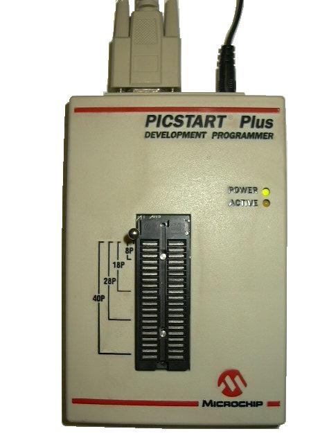
The programmer that we used for our project was the PicStart Plus Programmer available from Microchip.

The PicStart Plus Programmer

IDE
The other requirement is an IDE to use. Microchip provides an IDE as well as libraries for each of the
PIC models available free of charge from their website called MPLAB

Once you have the IDE running, go to the Configure menu and choose Select Device. Then choose the
PIC that you have from the drop down menu in the top left. This screen will show you if the programmer
you have is compatible with the PIC you're using. Green means fully compatible, yellow is beta support
and red is no compatibility.

Once you have the device selected go to Programmer>Select Programmer and choose the programmer from the list.

One last thing to make sure of when you are starting a new project. When you create a new assembly file, MPLAB
does not automatically add that file to the project, so make sure you manually do that in the project navigator menu.
There is also a very good code template available from the EE400/401 website.

Project Navigator Window

Once your code is complete, select Programmer>Enable Programmer to connect the programmer. If using a USB to Serial
connection, make sure that you configure your connection such that "Flow Control:" is set to "Hardware" and the
"Use FIFO buffers" checkbox is Unchecked. Once connected to the programmer, simply click on the "Program" button
in the top right to program and verify the PIC.

Useful MPLAB Properties

MPLAB does a number of things for you that make life much easier when programming PICs. First of all, it comes
packaged with libraries for each of the PIC models that MPLAB is able to program, which is almost all of them.
These libraries mostly contain #defines for all of the Special Purpose Registers and the controllable bits within them.
Therefore if you want to read a bit in the STATUS register, you don't have to look up the memory address, you can
simply use the name of it.

The MPASM assembler that MPLAB uses also provides many useful assembler directives. I'll talk about a few of the
more useful ones here:

banksel label - Used to automatically generate code to switch the current memory bank to whichever one contains
the register label.

__config expr - Used to set up the configuration bits of the PIC. There are a lot of different options which are all listed
in the library file.

data expr - This function is used to store a hex value at the current program memory location. Usually prefaced by a ORG directive
to set up the proper memory mapping. Also has similar expressions like da or dw for setting up data of different types.

udata and udata_shr - Used with the res command, these reserve and name registers for a certain memory bank, and shared
across all memory banks respectively.

org and code - Used to set the location of the subsequent code in memory. The code command also allows you to specify a name
for that code block.

pagesel - Similar to banksel but used to select which page of memory is used for goto and call commands.

res expr- Used to reserve expr number of registers.

Basics of PIC16 Programming

The PIC16F873A is an 8-bit processor with all 256bytes of addressable memory consisting of registers. However it has four
seperate banks of memory that can be switched between by setting bits in the STATUS register (or using the much simpler banksel
directive). It is very important to always make sure you double check which memory bank you are on before you try to access a
register. Similarly, the opcode for call and goto instructions is not long enough to address all of program memory, so the STATUS
register also has two bits PCLATH0:1 that control which page of memory is selected when a call or goto is issued. So once again
double check which page of memory you're pointing at and use pagesel to change if necessary.

All of the IO lines on the PIC are directly accessible by registers. The 16F873A has 3 banks of IO pins PORTA, PORTB and PORTC.
Each pin on these ports can be configured independently as input or output. This is done in the corresponding TRISX register. Where
a 1 corresponds to an input, and 0 is an output.

So, for example, if I wanted to output a high value on RA0, I would use the following code:

banksel        TRISA
bcf               TRISA, 0                      ;; Configure PORTA pin0 as an output
banksel        PORTA
movlw         0x01
movwf         PORTA                        ;; Write 0x01 to PORTA, setting pin 0 high

You might be wondering why I didn't use bsf to simply set the single pin of PORTA high. This is because bsf is one of many
Read-Modify-Write operations that the PIC utilizes. Since PORTA pins can be input or output pins and can be changed
during execution, the results of a RMW operation can be unpredictable, in this case, it is better to simply write a entire byte
into the register.

It is a similar operation to read from the IO lines:
banksel       TRISB
movlw        0xFF
movwf        TRISB                        ;; Configure all the pins of PORTB to be inputs
banksel       PORTB
movf           PORTB, W                ;; Move the contents of PORTB into the accumulator

One thing to note for the IO ports. We had trouble using pin RA4 for anything. There was a small mention in the data sheet of RA4
not working properly on some PIC models, and for us, we couldn't drive it high at all.

PIC Simulator

One of the major drawbacks of using the PICStart Plus programmer, is that it does not support debugging of the PIC software.
To remedy this I made use of a PIC Simulator IDE. The one I used is available for a free limited trial from OshonSoft.

This simulator comes with a built in assembler, but many of the assembler directives available in MPLAB do not work in the
simulator's assembler. However, you can simply assemble the code in MPLAB and load the hex file directly into the simulator.

PIC Simulator main screen

The main screen of the PIC simulator shows the value of all the registers, the program counter and accumulator, last and next instructions and the
time elapsed. The values of any of the SFRs can be changed by clicking on the specific bits, and the GPRs can be changed by clicking and entering
a new value. From this screen you can also change the rate of simulation, step through instructions and change various options such as the clock
speed of the processor.

PIC Simulator breakpoints

This screen shows the current position of the PC in the code, and allows you to place a breakpoint in the code.
Setting and clearing breakpoints is done by clicking on the desired line of code. For this stage it is often easier to
go to View>Program Memory in MPLAB to get a listing of the much easier to read version of the code, with memory
addresses.

PIC Simulator program memory editor

Since our project used program memory, this window was very important for us. However even if you are not using program
memory for storage, this screen is useful for changing the instructions stored in program memory, if you want to change something
slightly without reassembling the project.