By: Kristina Suen Partner: Anita Has Group 2
What you need:
- XBee development kit
- Two XBees
- Two ARM boards
This tutorial will go through steps to initialize the XBee, hook it up to the ARM board and send messages serially.
- Follow the quick start manual included in the XBee development kit
The XBee development kit comes with a CD and a quick start manual. (A copy of this manual can be found in the Links section). The included cd will install drivers for the XBee and X-CTU (the necessary software to change XBee settings). Once this initial set up has been completed, we can then start changing the XBee settings so that they can communicate with each other.
At the end of this step, you should have gone through all of the instructions and achieved the following:- Designated which XBee is the base and which is the remote
- Completed a range test on the two XBees
Note When you first power the XBees, the lights on the XBee should be on and one should be blinking, which indicates that it is in working mode. If none of the lights blink, then you have a faulty XBee - get a new one. - XBee settings
Before we actually change settings on the XBee, it's helpful to write down what settings we'll be changing. It will be necessary to change the following: Baud rate, Pan ID, DL, MY.- Baud rate: 38400
This is the baud rate of the ARM serial interface, therefore, we need to set the XBee at the same rate. - Pan ID 0x6666
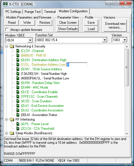
The Pan ID can be any 4-digit hex number. XBees on the same Pan ID will be able to communicate with each other, so it will be good to set this to something unique or else you might get some traffic of other XBees. Here, we set it to 0x6666. - DL 1
This is the address of the XBee that you will be communicating with. - MY 0
This is the address of the XBee you are changing settings for.
Settings for the second XBee will be exactly the same, except DL and MY will be switched. Note that DL and MY addresses does not necessarily need to be 1 and 0. They can be set to anything.Here's a summary:
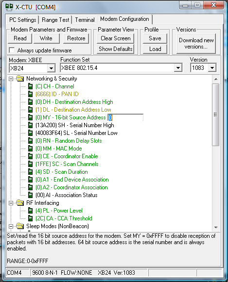
XBee settings Property Base Remote Baud rate 38400 38400 Pan ID 0x6666 0x6666 DL 1 0 MY 0 1 We will first set up the Base XBee: With the Base XBee connected to your computer, open X-CTU and navigate to the Modem Configuration tab.
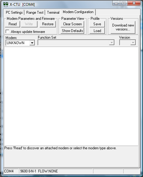
Click on 'Read'. You should get a listing of all of the settings that your XBee currently have and what you are able to change. Now that we already pre-determined the settings for each XBee, we can easily change the necessary fields. You should see something like the following: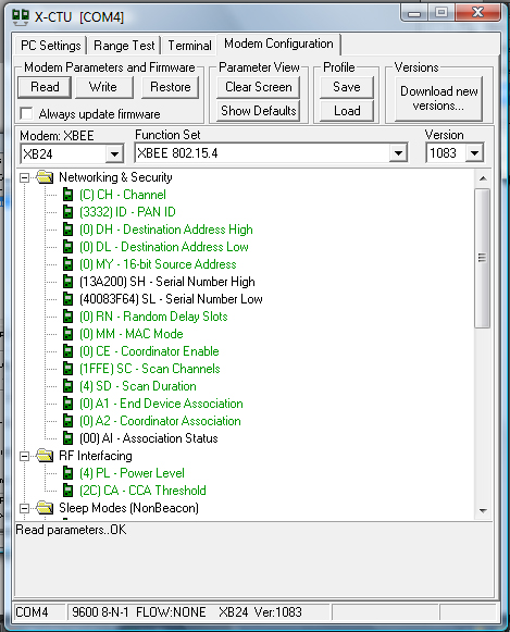
The following screens indicate the fields that you need to change: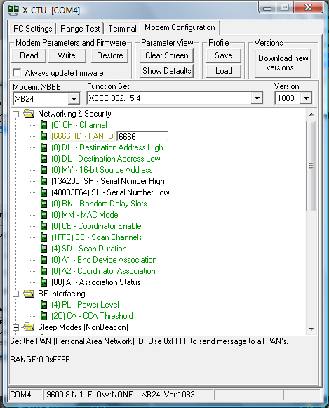
To set up the Remote XBee, you will have to connect it via USB to your computer and repeat the same steps.
- Baud rate: 38400
- Hooking it up to the ARM board
There is only really four pins on the XBee that you need to hook up: VCC (1), Dout(2), Din (3) and GND (10).Dout should be connected to a RX pin on the ARM board and Din should be connected to a TX pin (we used PA22 (RXD2) and PA21 (TXD2) for our RX and TX respectively). VCC should be connected to a 3.3V power source, and GND should be connected to a ground connection.
If theres no pin conflicts, you can hook up each XBees to their own ARM board using the same pin configurations.
Here's a summary:
Pin Connections XBee ARM Pin name Pin Pin name Pin Vcc 1 3.3V Dout 2 RXD2 PA22 Din 3 TXD2 PA21 GND 10 Ground - Send messages from one ARM board to another wirelessly using the XBees
Once you have each XBee connected to their respective boards, you can now send messages wirelessly! Since we hooked up the XBees to RXD and TXD pins on the ARM board, we can send messages using serial commands. Anything that we send to the TXD pin will be send to Dout on the XBee and by default, anything that the XBee receives on its Dout pin will be transmitted. Likewise, on the receiving XBee, anything that it receives on the Din pin will be automatically transferred to the RXD pin on the ARM board.As per Nancy, a useful way to see how to use at91 serial calls on the ARM board is to look at the other program in the atmel demos project in Lab 1. (We used the led_swing project.. the one you want to look at is the other one, which is an example of a terminal serial application). You can't use the exact same functions that is used in the demo, but you will get an idea of what include files you'll need and a good understanding of where to start.
To make it a little easier for you, here are some of the functions that I used:
- at91_usart_open
- at91_usart_get_status
- at91_usart_write
- at91_usart_read
- at91_usart_close
This should give you a good start on programming the ARM to send messages wirelessly using the XBees!
Links
XBee Quick Start Guide