Servo Signaling
This app note is intended to describe hobby servo signal timing, describe basic calculations required for implementing a servo driver, and give generalized examples for servo driver implementation in hardware. One nice aspect of servo signals is that most servo’s are very forgiving and will often allow you to make very large changes to the driving voltage and pulse frequency so long as the pulse widths remains the same. The servo used for testing was a Hitec HS-475HB which has survived a model aircraft crash so signals outside of the actual specifications should be used on a case by case basis, with proper testing and only when absolutely necessary.
Almost all hobby servos run at a nominal 5V but are tolerant to voltage fluctuations as they are often designed to run on unregulated power from a battery. Pushing the signal beyond 5 V is dangerous and very poorly documented for most servos I have come across and as such should not be attempted. Using signaling below 5 V can be done quite readily, on our test servo I was able to get correct operation using any Vhigh > 840 mV and = 5 V, I did not measure the maximum low voltage as I assumed it will always be 0 V. While unlikely there is the possibility for some servos to drive the input, briefly, with a 5 V signal, as such any pins used to drive a servo should be 5 V tolerant and it is recommended to put a resistor in series with the driving pin and the servo's signal pin. At 3.3 V a 1 kohm resistor has been recommended for the propeller chip and should be selected such that the maximum current of the pins protection diode and that of the pin its self are not exceeded should the pin be driven with 5 V while the pin is high(protection diode) or low(pin sink current).
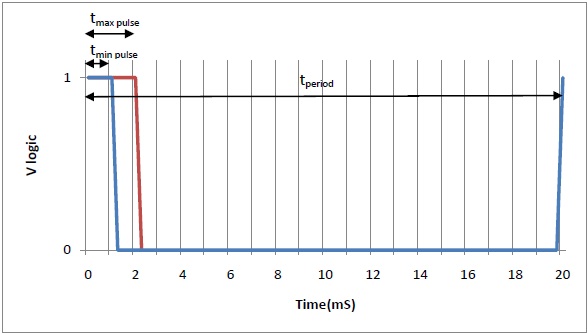
The timing specifications are as follows, Minimum pulse width (tmin pulse) = 1 mS, Maximum pulse width (tmax pulse) = 2 mS, and Signal period (tperiod) = 20 mS. This gives us a range of motion of ~ 90° with tmin pulse < tpulse < tmax pulse and a refresh rate of 50 Hz. For many servos the pulse width bounds can be expanded to 0.5 mS <-> 2.5 mS to get 180° of motion, and the period can be reduced to get a higher refresh rate which may or may not result in smoother operation. Using my test servo I was able to get proper operation using tmin pulse = 0.516 mS, tmax pulse = 2.52 mS and using periods within the range 5.04 – 25.0 mS. Our servo had noticeably less vibration at 200 Hz, period of 5 mS, than during normal operation.
One thing to note about extending the range of pulse widths is that the controller inside the servo is often capable of reading ranges beyond the physical limits of the servo which will result in excessive power consumption and heating at these limits. When setting upper and lower bounds for your pulse widths test the servo you will be working with without anything attached to the horn (the bit that moves) and listen for the servo straining at the upper and lower limits of your controller (tmin pulse & tmax pulse). If you can’t use the exact servo, use one of the same model and include some margin for error.
Servo Controller design pointers
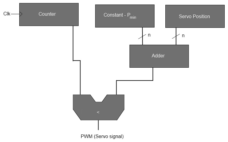
The example I will give for creating a servo controller uses a counter which rolls over to 0 at its maximum value, an adder, and a comparator as seen in Fig. 2. First of all this method breaks each pulse into a finite number of ticks, where the number of ticks in the range tmin pulse – tmax pulse gives you the resolution of your controller. There for the frequency of the clock required to drive the counter is:
Frq = Resolution / Active Pulse
Here Active Pulse = tmax pulse – tmin pulse and the resolution is the number of steps between the two end positions of the servo horn. The counter is set up to count from 0 to tperiod/(Active Pulse) * Resolution. Pmin is the minimum pulse width in ticks, Pmin = tmin pulse/(Active Pulse) * Resolution.