[ Previous |
Next |
Contents |
Glossary |
Home |
Search ]
AIX Version 4.3 System Management Guide: Operating System and Devices
Understanding System Boot Processing
Most users perform a hard disk boot when starting the system for general operations. The system finds all information necessary to the boot process on its disk drive.
When the system is started by turning on the power switch (a cold boot) or restarted with the reboot or shutdown commands (a warm boot), a number of events must occur before the system is ready for use. These events can be divided into the following phases:
- Read Only Storage (ROS) Kernel Init Phase
- Base Device Configuration Phase
- System Boot Phase
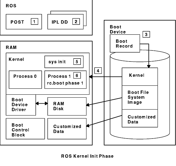
ROS Kernel Init Phase
The ROS Kernel Init Phase diagram illustrates the kernel initialization that takes place before the system boot process is started.
The ROS kernel initialization phase involves the following steps:
- The On-Chip Sequencer (OCS)
bring-up microprocessor (BUMP)
checks to see if there are any problems with the system motherboard. Control is passed to ROS, which performs a power-on self-test (POST).
-
The ROS initial program load (IPL)
checks the user boot list, a list of available boot devices. This boot list can be altered to suit your requirements using the bootlist command.
If the user boot list in NVRAM is not valid or if a valid boot device is not found, the default boot list is then checked. In either case, the first valid boot device found in the boot list is used for system startup.
If a valid user boot list exists in NVRAM, the devices in the list are checked in order. If no user boot list exists, all adapters and devices on the bus are checked. In either case, devices are checked in a continuous loop until a valid boot device is found for system startup.
Note:
The system maintains a default boot list located in ROS and a user boot list stored in NVRAM, for a normal boot. Separate default and user boot lists are also maintained for booting from the Service key position.
- When a valid boot device is found, the first record or program sector number (PSN) is checked. If it is a valid boot record, it is read into memory and is added to the initial program load (IPL) control block in memory. Included in the key boot record data are the starting location of the boot image on the boot device, the length of the boot image, and instructions on where to load the boot image in memory.
- The boot image is read sequentially from the boot device into memory starting at the location specified in the boot record. The disk boot image consists of the kernel, a RAM file system, and base customized device information.
- Control is passed to the kernel, which begins system initialization.
- Process 1 executes init, which executes phase 1 of the rc.boot script.
When the kernel initialization phase is completed, base device configuration begins.
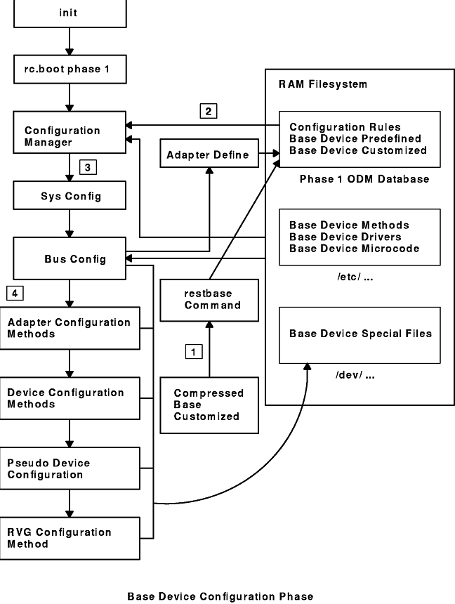
Base Device Configuration Phase
The Base Device
Configuration Phase diagram illustrates this part of the boot process.
The init process starts the
rc.boot script. Phase 1 of the rc.boot script performs the base
device configuration, and it includes the following steps:
- The boot script calls the
restbase program to build the customized Object Database
Manager (ODM) database in the RAM file system from the compressed
customized data.
- The boot script starts the
configuration manager, which accesses phase 1 configuration rules to
configure the base devices.
- The configuration manager starts the
sys, bus, disk, SCSI, and the Logical Volume
Manager (LVM) and rootvg volume group (RVG) configuration methods.
- The configuration methods load the
device drivers, create special files, and update the customized data
in the ODM database.
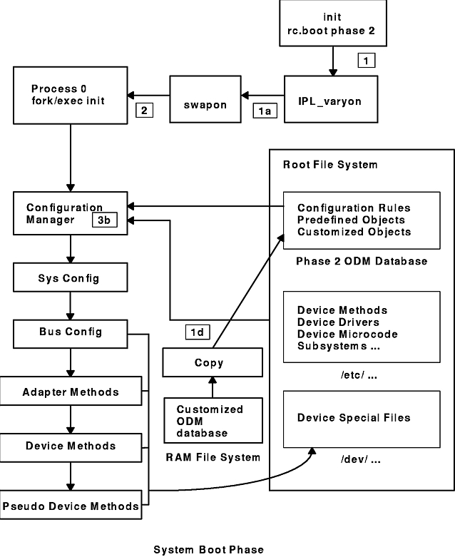
System Boot Phase
The System Boot
Phase diagram illustrates the steps involved in the system boot process.
- The init process starts phase 2 execution of the rc.boot script. Phase 2 of rc.boot includes the following steps:
- Call the ipl_varyon program to vary on the rootvg volume group (RVG).
- Mount the hard disk file systems onto the RAM file system.
- Run swapon to start paging.
- Copy the customized data from the ODM database in the RAM file system to the ODM database in the hard disk file system.
- Unmount temporary mounts of hard disk file systems and then perform permanent mounts of root, /usr, and /var.
- Exit the rc.boot script.
- After phase 2 of rc.boot, the boot process switches from the RAM file system to the hard disk root file system.
- Then the init process executes the processes defined by records in the /etc/inittab file. One of the instructions in the /etc/inittab file executes phase 3 of the rc.boot script, which includes the following steps:
- Mount /tmp hard disk file system.
- Start the configuration manager phase 2 to configure all remaining devices.
- Use the savebase command to save the customized data to the boot logical volume.
- Exit the rc.boot script.
At the end of this process, the system is up and ready for use.
[ Previous |
Next |
Contents |
Glossary |
Home |
Search ]